Long-distance distributed large-dynamic microwave optical fiber stable-phase transmission system and method

A stable phase transmission and distributed technology, applied in electromagnetic wave transmission system, optical fiber transmission, transmission system, etc., can solve the problem of large compensation range, achieve high-precision delay compensation, large dynamic range, and reduce the effect of compensation range requirements

Active Publication Date: 2020-02-04
扬州船用电子仪器研究所
View PDF3 Cites 1 Cited by
  • Summary
  • Abstract
  • Description
  • Claims
  • Application Information

AI Technical Summary

Problems solved by technology

[0004] The present invention aims to solve the problem that the compensation range is too large in the prior art in order to ensure the phase consistency of the broadband microwave signal in the case of long-distance transmission and high environmental adaptability and to perform absolute compensation on the signals of each distributed site. Problem, a long-distance distributed large dynamic microwave optical fiber phase-stable transmission system is proposed, characterized in that the transmission system includes a main signal optical transmission module, a reference optical transceiver module, an amplitude and phase monitoring and control module, a delay compensation module, Dispersion compensation and optical amplification module, signal return module and main signal optical receiving module;

Method used


Image

  • Long-distance distributed large-dynamic microwave optical fiber stable-phase transmission system and method
  • Long-distance distributed large-dynamic microwave optical fiber stable-phase transmission system and method
  • Long-distance distributed large-dynamic microwave optical fiber stable-phase transmission system and method

Examples


Embodiment Construction

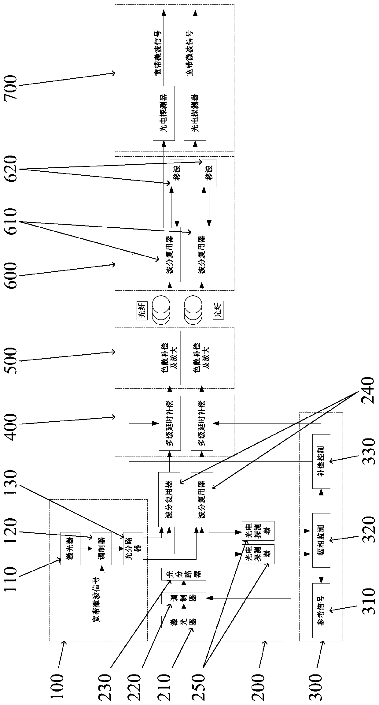
[0044] Through the following examples, combined with the attached Figure 1-3 , the technical solution of the present invention will be further specifically described.

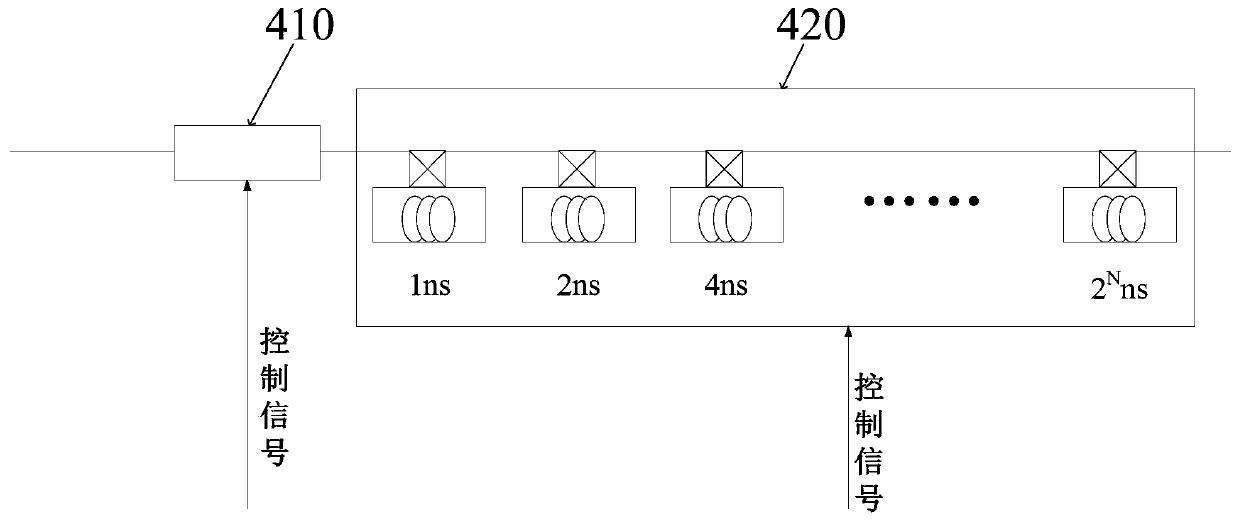
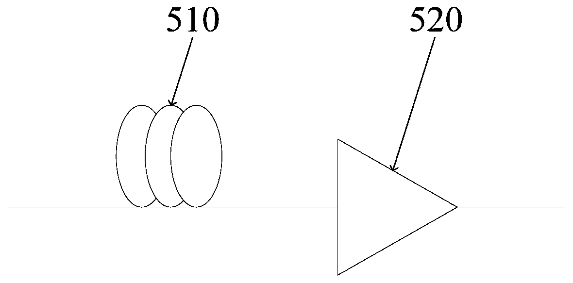
[0045] as attached figure 1 As shown, a schematic structural diagram of a long-distance distributed large dynamic microwave optical fiber phase-stable transmission system provided by an embodiment of the present invention is illustrated by taking two sub-sites as an example. As shown in the figure, the long-distance distributed large dynamic microwave optical fiber phase-stable transmission system in this embodiment includes a main signal optical transmission module 100, a reference optical transceiver module 200, an amplitude and phase monitoring and control module 300, a delay compensation module 400, A dispersion compensation and optical amplification module 500 , a signal return module 600 , and a main signal optical receiving module 700 .

[0046] The interior of the main signal light emitting module 100 ...


PUM


Abstract

The invention provides a long-distance distributed large-dynamic microwave optical fiber stable-phase transmission system which comprises a main signal light-emitting module, a reference light receiving and transmitting module, an amplitude-phase monitoring and control module, a delay compensation module, a dispersion compensation and light amplification module, a signal return module and a main signal light receiving module, wherein the amplitude-phase monitoring and control module further comprises a reference signal unit, an amplitude-phase monitoring unit and a compensation control unit; the reference signal unit adopts a variable frequency signal source; and the amplitude-phase monitoring unit directly performs phase discrimination and amplitude monitoring among the reference signalsreturned by each sub-station. According to the invention, the reference signal unit can change the frequency of the reference signal in real time, so as to obtain higher phase monitoring precision; the amplitude-phase monitoring unit directly carries out phase discrimination and amplitude monitoring on the reference signals returned by the sub-stations, only relative compensation between the sub-stations needs to be carried out, the compensation range requirement of the delay compensation module is lowered, and meanwhile the complexity degree and cost requirement of the system are lowered.

Description

technical field [0001] The invention relates to the technical field of microwave signal phase-stable transmission of optical fiber, in particular to a long-distance distributed large dynamic microwave optical fiber phase-stable transmission system and method. Background technique [0002] The optical fiber transmission technology of microwave signals is to transmit microwave signals through optical fibers, and utilizes the unique advantages of optical fibers such as low loss, high stability, and strong anti-electromagnetic interference ability to achieve low-loss long-distance transmission that cannot be achieved by traditional cable transmission. However, the fragility of the fiber itself makes it easily affected by the external environment, such as temperature, stress and other factors, resulting in changes in the local refractive index of the fiber, which eventually leads to random changes in signal delay during optical transmission, resulting in phase jitter , in order t...

Claims


Application Information

Patent Timeline
Patent Type & Authority Applications(China)
IPC IPC(8): H04B10/25H04B10/2525
CPCH04B10/2525
Inventor 林桂道范晶晶张昀陈奇余博昌
Owner 扬州船用电子仪器研究所
Why Eureka
Try Eureka