
Anti-ignition gear and magnetron sputtering coating device

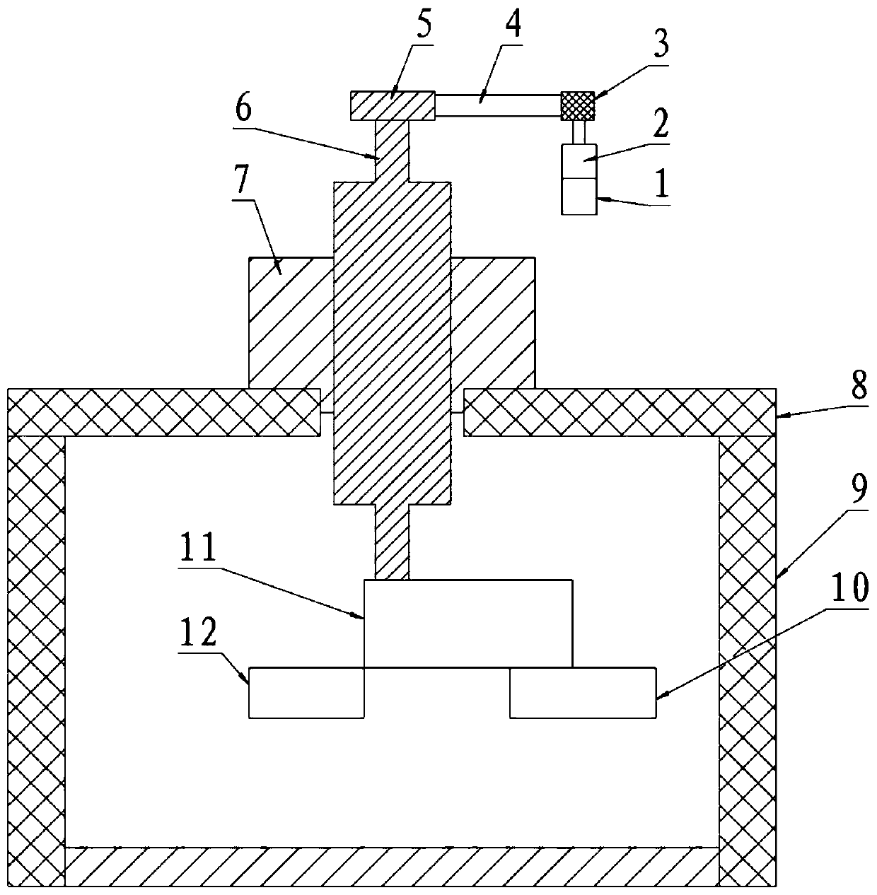
A technology of magnetron sputtering coating and gears, which is applied in sputtering coatings, hoisting devices, portable lifting devices, etc., can solve the problems of gear keyway 15 damage, failure of upper electrode operation, and low strength of gears, etc., to avoid Effects of unreliable operation, improved safety and reliability, and increased operational stability

Active Publication Date: 2020-02-07
BEIJING NAURA MICROELECTRONICS EQUIP CO LTD
View PDF16 Cites 0 Cited by
  • Summary
  • Abstract
  • Description
  • Claims
  • Application Information

AI Technical Summary

Problems solved by technology

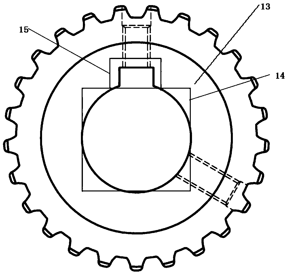
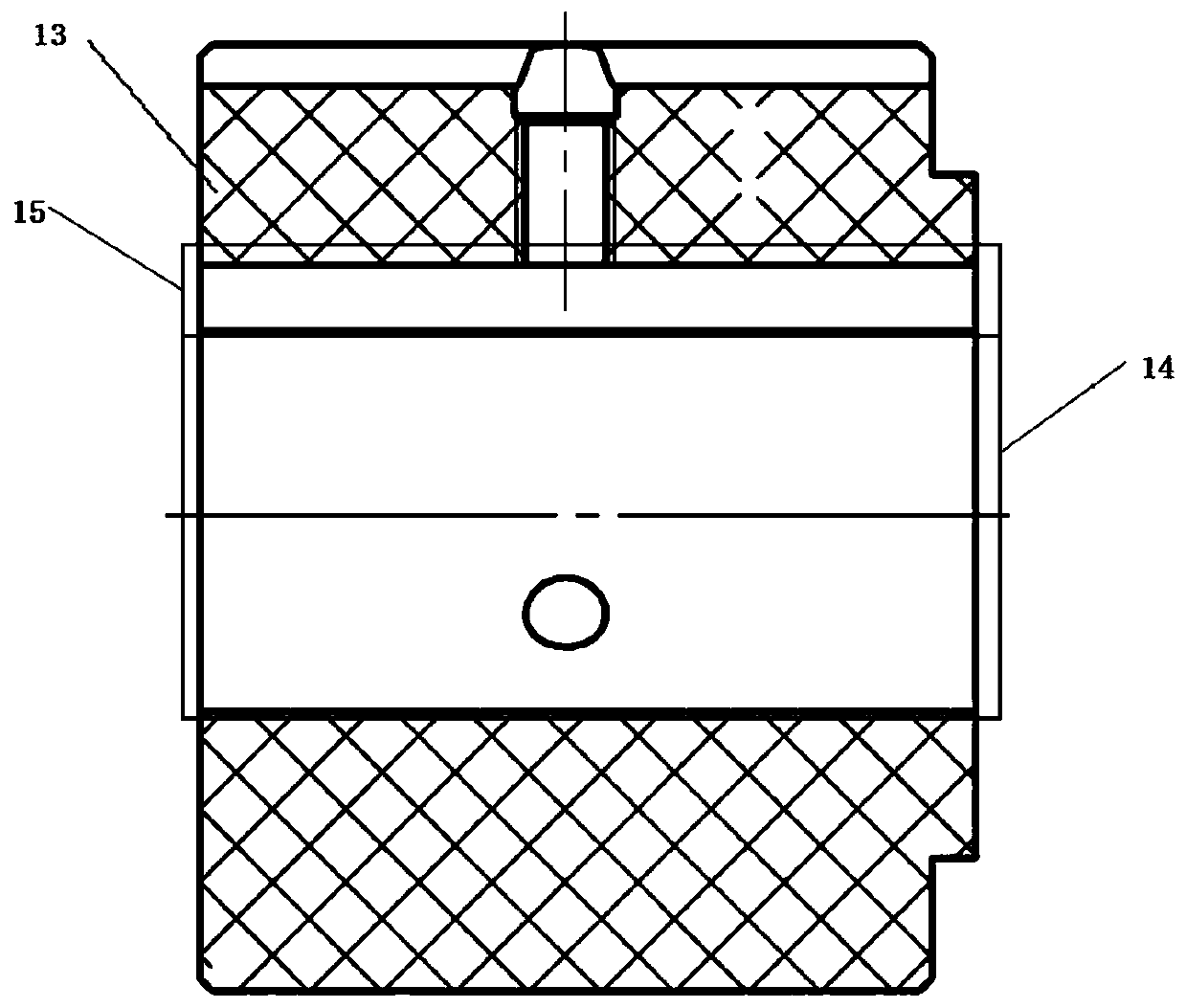
[0007] Existing gear structure such as Figure 2 and Figure 3, the gear 13 is made of cast nylon (also known as MC901 material or cast nylon) material as a whole. MC901 material has an insulating effect and can interrupt the formed electrical circuit, which solves the ignition problem of the belt to a certain extent, but Due to the soft material of MC901, the overall strength of the gear is not high. In the case of vibration or after a long time of variable speed operation, the loose top screw of the gear 13 may easily cause eccentric wear of the inner circular shaft hole 14 in contact with the reducer shaft. What's more, the key installed on the shaft may damage the gear keyway 15, causing the upper electrode to fail in operation

Method used


Image

  • Anti-ignition gear and magnetron sputtering coating device
  • Anti-ignition gear and magnetron sputtering coating device
  • Anti-ignition gear and magnetron sputtering coating device

Examples


Embodiment Construction

[0043]The present invention will be described in more detail below with reference to the accompanying drawings. Although preferred embodiments of the invention are shown in the drawings, it should be understood that the invention may be embodied in various forms and should not be limited to the embodiments set forth herein. Rather, these embodiments are provided so that this disclosure will be thorough and complete, and will fully convey the scope of the invention to those skilled in the art.

[0044] Figure 4 It shows a schematic diagram of the axial end face structure of an anti-sparking gear according to an embodiment of the present invention, Figure 5 It shows a schematic diagram of the radial structure of an anti-sparking gear according to an embodiment of the present invention;

[0045] Such as Figure 4 , Figure 5 As shown, the anti-sparking gear 100 provided by the embodiment of the present invention includes:

[0046] The gear body, the gear body includes an i...


PUM


Abstract

The invention discloses an anti-ignition gear and a magnetron sputtering coating device. The anti-ignition gear comprises a gear body. The gear body comprises an insulated gear ring and a strengthenedlantern ring sleeved with the insulated gear ring. The outer wall of the strengthened lantern ring is connected with the inner wall of the insulated gear ring. The outer wall of the strengthened lantern ring is attached to the inner wall of the insulated gear ring. Multiple gear teeth are arranged on the outer wall of the insulated gear ring. The insulated gear ring is insulated, and the strengthof the strengthened lantern ring is higher than that of the insulated gear ring. Through the adoption of the dual-layer structure of the insulated gear ring made of an insulation material and the strengthened lantern ring, insulativity of the gear and an external connector is achieved, meanwhile, the overall mechanical strength of the gear can be improved, especially the strength of a shaft holecan be increased, the shaft hole can be prevented from being worn and destroyed by an externally-connected rotating shaft, and therefore the operating stability of a transmission mechanism adopting the anti-ignition gear is increased.

Description

technical field [0001] The invention relates to the field of semiconductor manufacturing equipment, in particular to an anti-sparking gear and a magnetron sputtering coating device. Background technique [0002] Copper sputtering has been developed rapidly due to its advantages such as low conductivity and reduced electron migration. The sputtering process of the copper target is completed with the rotation of the top magnetron, and the target will be sputtered only at the position where the magnetron passes. The magnetron rotates one cycle at a constant speed on the back of the target, which is equivalent to a full target sputtering on the entire target. [0003] The upper electrode of the copper cavity generally uses a planetary magnetron. The planetary magnetron increases the corrosion area of ​​the target, and at the same time optimizes the electrical design to realize the variable speed control of the magnetron to meet the needs of the 28nm process. The magnetron's li...

Claims


Application Information

Patent Timeline
Patent Type & Authority Applications(China)
IPC IPC(8): F16H55/06F16H55/12F16H55/17C23C14/35
CPCF16H55/06F16H55/12F16H55/17C23C14/35
Inventor 张立茂王涛佘清
Owner BEIJING NAURA MICROELECTRONICS EQUIP CO LTD
Learn More