Solar heat absorber capable of being driven to rotate and translate through wind power and working method thereof

A solar heat absorber and wind power technology, applied in the field of solar thermal utilization, can solve the problems of unrealized movement along the axial direction, inability to solve energy flow, power grid consumption, etc., achieve simple processing and manufacturing, improve economic performance, and improve cost performance Effect

Pending Publication Date: 2020-02-07
HUNAN UNIV OF SCI & TECH
View PDF2 Cites 1 Cited by
  • Summary
  • Abstract
  • Description
  • Claims
  • Application Information

AI Technical Summary

Problems solved by technology

However, the heat absorber in the prior art only realizes the rotational movement along the circumferential direction, but the movement along the axial direction does not realize
This cannot solve the problem of non-uniform energy flow along the axial direction
In fact, the non-uniformity of the energy flow distribution along the axial depth direction of the cavity receiver is more signific

Method used


Image

  • Solar heat absorber capable of being driven to rotate and translate through wind power and working method thereof
  • Solar heat absorber capable of being driven to rotate and translate through wind power and working method thereof
  • Solar heat absorber capable of being driven to rotate and translate through wind power and working method thereof

Examples


Embodiment 1

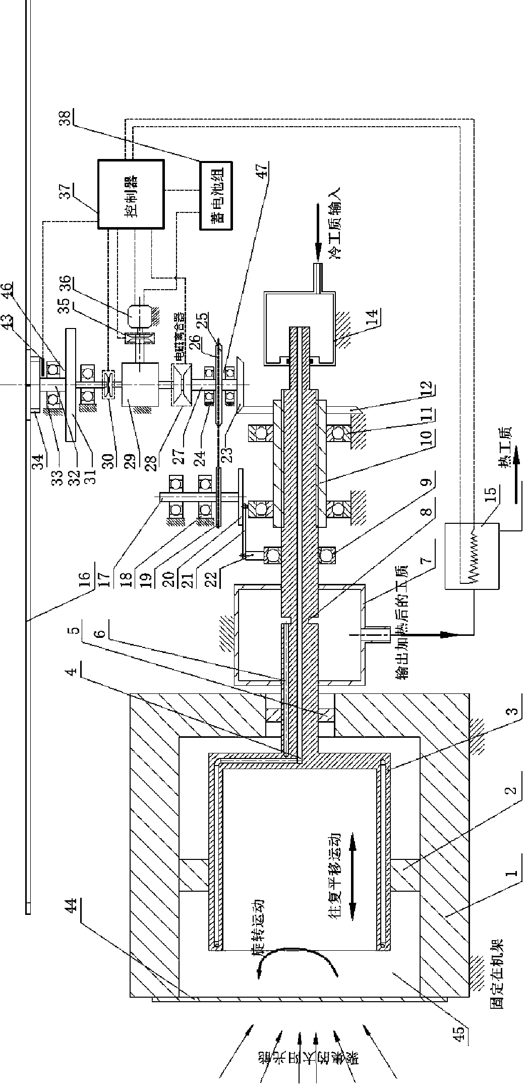
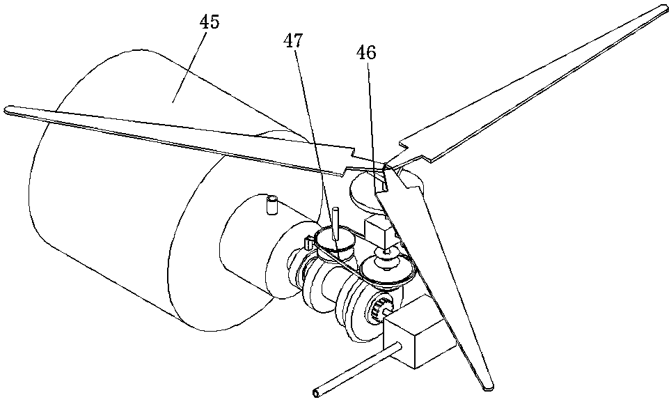
[0037] Figure 1-3 Shown is an embodiment of the present invention, which includes a cavity heat sink 45, a wind turbine unit 46, a transmission device 47, a DC motor 36, a battery pack 38, a controller 37 and a reheater 15.

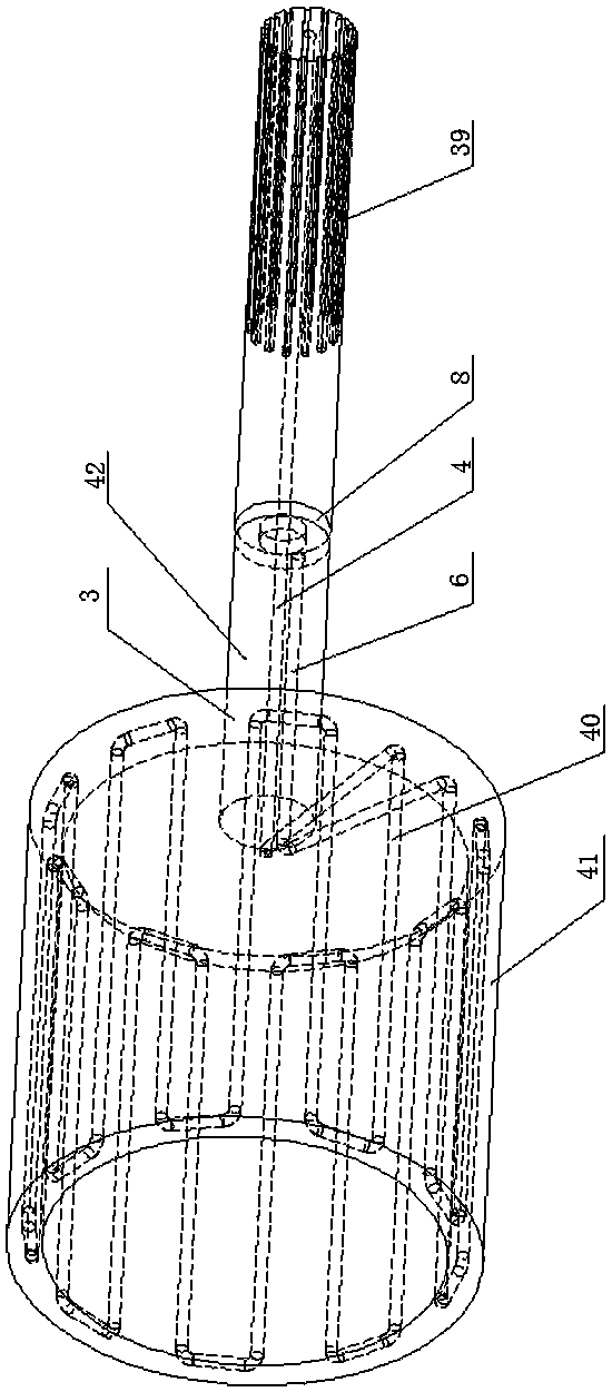
[0038] The cavity heat absorber 45 includes a heat preservation cavity 1, a heat absorption body 3, a hot working medium collection cavity 7 and a cold working medium collection cavity 14. The heat preservation cavity 1 has a cylindrical structure and is fixedly installed on the frame B. The open end of the heat preservation cavity 1 is provided with quartz glass to reduce the heat loss of the heat sink. The heat absorption body 3 includes a cylindrical heat absorption cavity 41 and a working fluid transport shaft 42. The working fluid transport shaft 42 is installed on the bottom plate of the heat absorption cavity 41 and is coaxial with the heat absorption cavity 41. The heat absorption cavity 41 is installed in the heat preservation cavity 1 through the...

Embodiment 2

[0044] Figure 4 Shown is another embodiment of the invention. It is similar to the structure of the first embodiment, except that the only difference lies in the working medium flow connection structure between the working medium transport shaft 42 and the cold working medium collection cavity 14 in the heat absorption body 3. The inlet of the working medium input channel 4 in the working medium transport shaft 42 is connected with the spherical hinge at one end of the flexible metal tube 13. The flexible metal tube 13 is a fluid working medium transmission element with spherical hinges at both ends. The ball hinge at the other end of the metal tube 13 is connected to the circular orifice of the cold working medium collection cavity 14, so as to realize the flow of the cold working medium collection cavity 14 to the working medium input flow channel 4 in the working medium transport shaft 42 and satisfy Rotation and translation movement conditions of the heat absorbing body 3....


PUM


Abstract

The invention discloses a solar heat absorber capable of being driven to rotate and translate through wind power and a working method thereof. The solar heat absorber capable of being driven to rotateand translate through the wind power comprises a rack, a cavity heat absorber, a wind turbine unit, a direct current motor, a storage battery pack and a controller, wherein the cavity heat absorber comprises a heat insulation cavity, a heat absorption body, a hot working medium collecting cavity and a cold working medium collecting cavity, the heat insulation cavity is of a cylindrical structureand is fixedly mounted on the rack, the heat absorption body comprises a cylindrical heat absorption cavity and a working medium transport shaft, the working medium transport shaft is installed on a heat absorption cavity bottom plate and is coaxial with the heat absorption cavity, the heat absorption cavity is installed in the heat insulation cavity, the working medium transport shaft penetratesout of a through hole in the heat insulation cavity bottom plate, and the heat absorption cavity can rotate and translate relative to the heat insulation cavity. The solar heat absorber not only realizes the rotation and reciprocating translation of the solar cavity heat absorber, but also realizes the power supply driving of stored electricity of the wind generating set when no wind exists or wind power is insufficient, and wind energy can be converted into electric energy and stored.

Description

Technical field [0001] The invention relates to the field of solar light and heat utilization, in particular to a solar heat absorber driven by wind energy to rotate and translate and a working method thereof. Background technique [0002] Solar energy is a clean, environmentally friendly and widely distributed renewable energy. Solar thermal power generation (CSP) technology is one of the important ways to efficiently develop and utilize solar energy. CSP technology has three typical methods: trough type, dish type and tower type. The latter two types can achieve high-temperature operation (usually above 600°C), so their light-heat-electric conversion efficiency is the highest. Dish and tower systems usually use large-area concentrators to gather solar radiation energy on the receiver (or heat sink), and then heat the fluid working medium inside the receiver, and then drive the heat engine to do work through the thermal cycle process , And drive the generator set to generate po...

Claims


Application Information

Patent Timeline
IPC IPC(8): F24S20/20F24S23/30F24S30/425F24S30/20F24S80/60
CPCF24S20/20F24S23/30F24S30/20F24S30/425F24S80/60Y02E10/47
Inventor 颜健封鸿嶂唐俊豪彭佑多刘永祥田勇
Owner HUNAN UNIV OF SCI & TECH
Why Eureka
Try Eureka