
Comprehensive optical monitoring system

An optical monitoring and grating technology, applied in the field of atmospheric spectral radiation detection, can solve the problems of inability to accurately locate pollution sources, insufficient global coverage, low time resolution, etc., achieve compact structure, increase ground time resolution, and spectral resolution high effect

Inactive Publication Date: 2020-02-07
OCEAN UNIV OF CHINA
View PDF8 Cites 0 Cited by
  • Summary
  • Abstract
  • Description
  • Claims
  • Application Information

AI Technical Summary

Problems solved by technology

Most of these atmospheric monitors monitor ozone with a narrow band, and rarely monitor other atmospheric trace gases
In addition, the spatial resolution of these instruments is low, and the pollution source cannot be accurately located. The global coverage of many instruments is insufficient, the return visit period is long, and the time resolution is low.

Method used


Image

  • Comprehensive optical monitoring system
  • Comprehensive optical monitoring system
  • Comprehensive optical monitoring system

Examples


Embodiment Construction

[0039] The technical solution in this application will be described below with reference to the accompanying drawings.

[0040] Reference will now be made in detail to the exemplary embodiments, examples of which are illustrated in the accompanying drawings. When the following description refers to the accompanying drawings, the same numerals in different drawings refer to the same or similar elements unless otherwise indicated. The implementations described in the following exemplary embodiments do not represent all implementations consistent with this application. Rather, they are merely examples of apparatuses and methods consistent with aspects of the present application as recited in the appended claims.

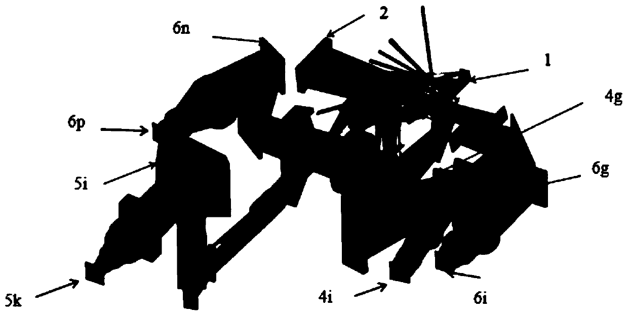
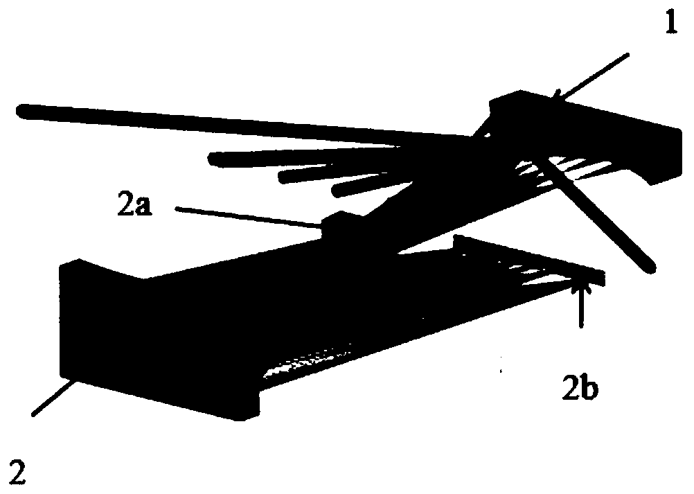
[0041] Such as figure 1 and figure 2 As shown, the integrated optical monitoring system provided in the embodiment of the present application is a spaceborne imaging system based on nadir observation, and adopts the working mode of push-broom imaging to detect atmos...


PUM


Abstract

The invention provides a comprehensive optical monitoring system, which comprises a telescope, an ultraviolet UV spectrometer, an ultraviolet visible UVIS spectrometer, a near-infrared NIR spectrometer and a short wave infrared SWIR spectrometer; the filed of view of the telescope is greater than 100 DEG; the working band of the telescope covers the outer band, the visible band, the near-infraredband and the short waved infrared band; the UV spectrometer, the UVIS spectrometer and the NIR spectrometer use the raster to divide light; the SWIR spectrometer uses the immersion raster to divide light; and, the UV spectrometer, the UVIS spectrometer, the NIR spectrometer and the SWIR spectrometer share the telescope. The application provides a comprehensive optical monitoring system with wide spatial coverage area, high spatial resolution, wide band and high spatial resolution.

Description

technical field [0001] The invention relates to the technical field of atmospheric spectral radiation detection, in particular to an integrated optical monitoring system. Background technique [0002] So far, climate and environmental disasters caused by the deviation of the earth-atmosphere system from its quasi-equilibrium state (such as global warming has been recognized as a fact) have seriously threatened the sustainable development of human society. In order to study the interrelationship between human activities, the Earth system and the space environment, global change and its scientific basis "Earth System Science" has become the focus and hot issue of current interdisciplinary research. In order to understand and solve this problem, one of The important means are to use various sensors (from ultraviolet to microwave, radio wave) to conduct long-term, large-scale and high-precision dynamic monitoring of the earth's surface and atmospheric system as a whole, especial...

Claims


Application Information

Patent Timeline
IPC IPC(8): G01N21/31G01N21/33G01N21/3504G01N21/359G01N21/01G01N21/17
CPCG01N21/01G01N21/17G01N21/31G01N21/33G01N21/3504G01N21/359G01N2021/0112G01N2021/1765G01N2021/178G01N2021/1789G01N2021/3129
Inventor 薛庆生田中天王福鹏
Owner OCEAN UNIV OF CHINA
Learn More