
IGBT junction temperature estimation method based on IGBT thermoelectric coupling model

A thermoelectric coupling and thermal coupling technology, which is applied in the electric power field, can solve the problems of difficult to measure the temperature rise curve and inapplicable thermal parameters, and achieves the effect of fast calculation speed, simple operation and simplified solution process.

Pending Publication Date: 2020-02-07
BEIJING NORTH HUADE NEOPLAN BUS
View PDF12 Cites 17 Cited by
  • Summary
  • Abstract
  • Description
  • Claims
  • Application Information

AI Technical Summary

Problems solved by technology

[0004] In order to solve the above-mentioned technical problems, the present invention provides a method to improve the reliability and service life of the IGBT of the inverter, which overcomes the shortcomings that the thermal parameters are not applicable in the case of high current and the temperature rise curve is not easy to measure, and simplifies the solution process. The established off-line model, the IGBT junction temperature estimation method based on the IGBT thermoelectric coupling model with fast calculation speed

Method used


Image

  • IGBT junction temperature estimation method based on IGBT thermoelectric coupling model
  • IGBT junction temperature estimation method based on IGBT thermoelectric coupling model
  • IGBT junction temperature estimation method based on IGBT thermoelectric coupling model

Examples


Embodiment Construction

[0042] combined with Figure 1-18 , the present invention will be further described.

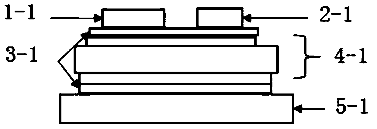
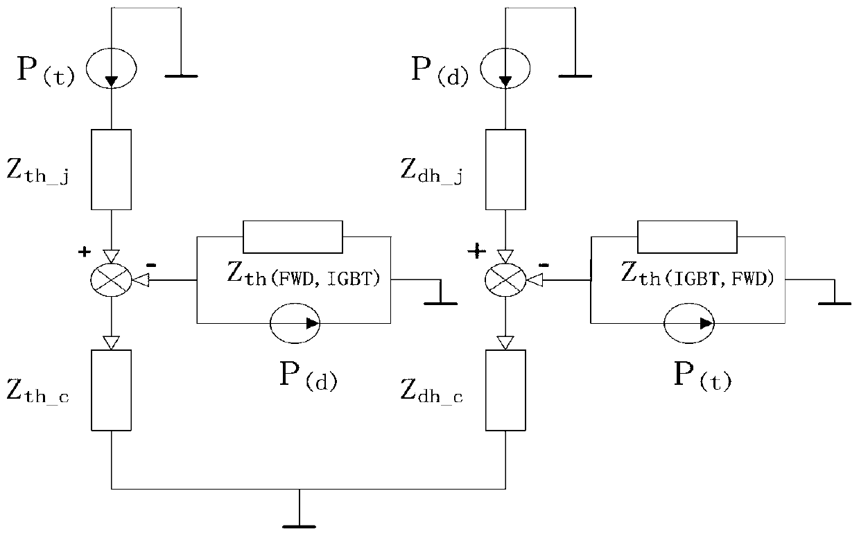
[0043] figure 1 is the heat transfer route of the IGBT, wherein the chip 1-1, the diode 2-1, the soldering layer 3-1, the DCB board 4-1, and the base plate 5-1 are copper base plates. Considering the two-dimensional improved model established by the interaction between the reverse diode and the IGBT, a two-dimensional coupling thermal resistance network model is established. Because the one-dimensional thermal resistance network model has certain limitations, a two-dimensional coupled thermal resistance network model is established, such as figure 2 As shown, where Pt: IGBT power loss, Pd: anti-parallel diode power loss, Zth-j: IGBT junction-case thermal impedance, Zth-c: case-to-ambient thermal impedance below the IGBT, Zth(FWD,IGBT): IGBT Relative to the diode thermal impedance, Zdh-j: junction-to-case thermal impedance of the diode, Zdh-c: case-to-ambient thermal impedance below the d...


PUM


Abstract

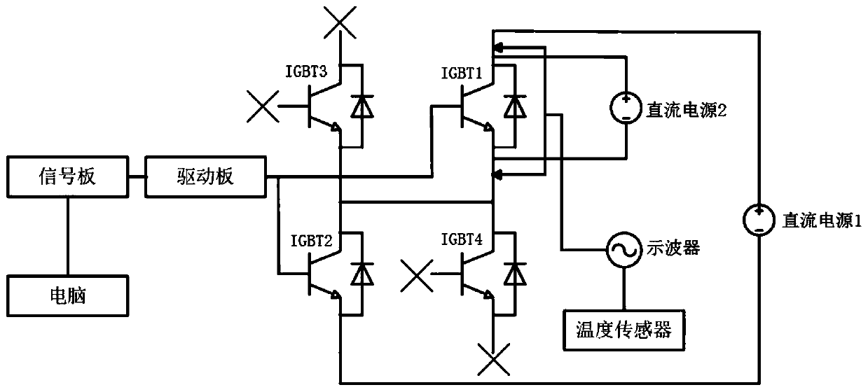
The invention belongs to the technical field of electric power, and particularly relates to an IGBT junction temperature estimation method based on an IGBT thermoelectric coupling model, which is characterized in that an experimental platform based on a thermosensitive parameter method and a double-pulse test principle, a cross thermal coupling model and a power loss model are established; a two-dimensional coupling thermal resistance network model is created by using a thermosensitive parameter method to extract transient thermal impedance parameters, and a cross thermal coupling model is created ; iGBT switching characteristics are tested based on a double-pulse test principle, power loss model parameters are obtained, and a power loss model is built; and the IGBT thermoelectric couplingmodel is coupled based on the cross thermal coupling model and the power loss model, and estimating the IGBT junction temperature. The reliability of IGBT of the inverter is improved, the service life of the IGBT of the inverter is prolonged, the defects that thermosensitive parameters are inapplicable under the condition of large current and a temperature rise curve is not easy to measure are overcome, the solving process is simplified, an offline model is established, and the calculation speed is high.

Description

technical field [0001] The invention belongs to the field of electric power technology, and in particular relates to an IGBT junction temperature estimation method based on an IGBT thermoelectric coupling model. Background technique [0002] The development trend of new energy vehicles and intelligent vehicles is very hot, and people are widely optimistic about it, which has also led to the soaring price of semiconductor chips in recent years. The motor is an important part of the new energy electric vehicle drive system, and its efficient and reliable electric speed control system is the cornerstone of motor control. The power device is the core component of the motor speed control system. Its IGBT (insulated gate bipolar transistor) is a high-switching frequency and large-capacity switching device. The switching frequency can be as high as tens of thousands of times, and the current and voltage can reach thousands of amperes Volts can be regarded as the "heart" of modern ...

Claims


Application Information

Patent Timeline
IPC IPC(8): G06F30/20G06F119/08
CPCY02E60/00
Inventor 闫志峰罗高华王晶高云龙李海玲窦佳欢
Owner BEIJING NORTH HUADE NEOPLAN BUS
Learn More