Method for preparing connection structure between porous surface structure and substrate

A surface structure and porous structure technology, applied in welding equipment, manufacturing tools, resistance welding equipment, etc., can solve problems such as low bonding efficiency, high heat generated by contact, and damage to porous structures

Active Publication Date: 2020-02-11
JY MEDICAL DEVICES SHANGHAI CO LTD +1
View PDF16 Cites 3 Cited by
  • Summary
  • Abstract
  • Description
  • Claims
  • Application Information

AI Technical Summary

Problems solved by technology

However, for high-porosity structures, when resistance welding is used to directly connect the porous structure and the substrate, the bonding efficiency is low at this time, resulting in insufficient welding bonding strength or requiring too high a current to achieve sufficient welding strength, The latter causes the contact between the upper electrode and the upper surface of the porous structure to generate too much heat so that the surface of...

Method used


Image

  • Method for preparing connection structure between porous surface structure and substrate
  • Method for preparing connection structure between porous surface structure and substrate
  • Method for preparing connection structure between porous surface structure and substrate

Examples


Embodiment 1

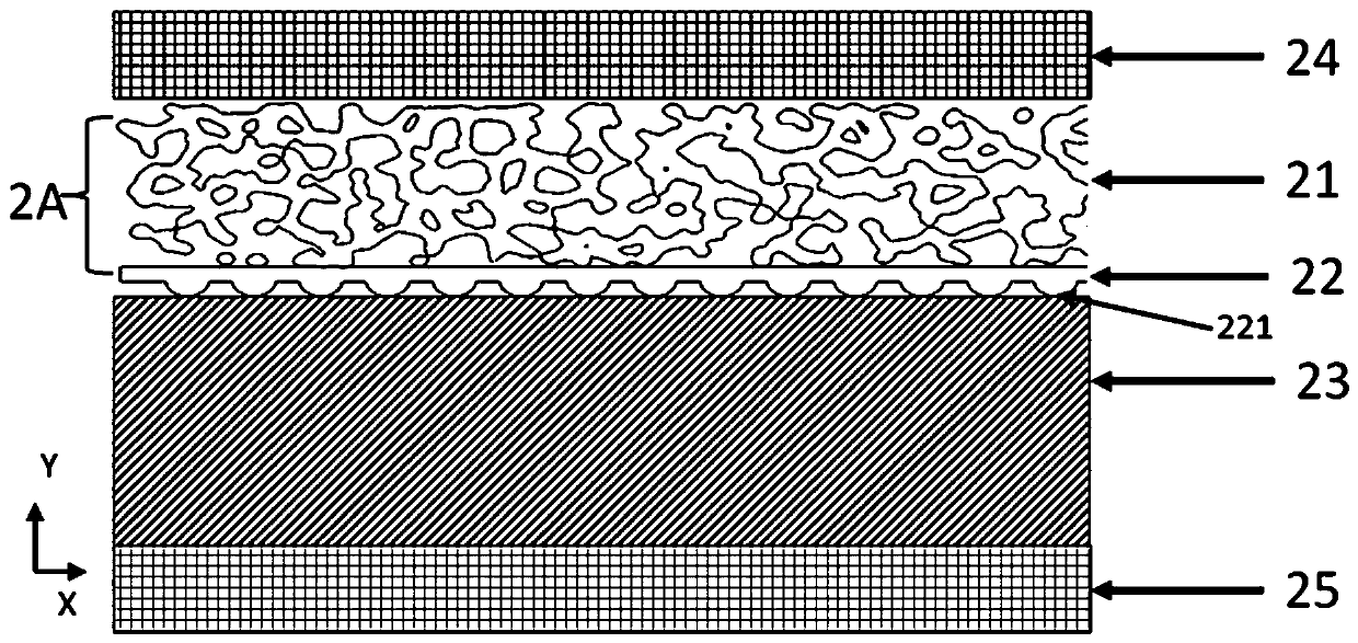
[0108] Such as figure 2 As shown, the present invention provides a connection structure, including a substrate 23 , an intermediate body 22 , and a porous surface structure 21 . Wherein, the porous structure of the porous surface structure 21 includes many staggered supports (or beams), and some multi-directional through-through, regular or irregular pores are formed between these supports (or beams). The intermediate body 22 is located between the porous surface structure 21 and the substrate 23 . Optionally, the intermediate body 22 is a non-porous bottom plate, that is, a solid bottom plate. Both the porous surface structure 21 and the intermediate body 22 are made of conductive materials (such as metal materials). The porous surface structure 21 and the intermediate body 22 are integrally formed, for example, by 3D printing additive manufacturing process, or vapor deposition process.

[0109] For example, the base 23 is solid, which is beneficial to the overall strengt...

Embodiment 2

[0120] For the first embodiment above, the porous surface structure 21 is a structure with a certain porosity, the intermediate body 22 is located between the porous surface structure 21 and the substrate 23 , and the intermediate body 22 is a non-porous bottom plate 22 . In fact, the intermediate body 22 can be the solid plate described in the first embodiment, or the porous structure with low porosity described in the second embodiment.

[0121] Therefore, the main difference from Embodiment 1 is that the connection structure of Embodiment 2 includes a first porous structure 41 in a high-porosity region, a second porous structure 42 in a low-porosity region (as an intermediate), and a substrate 43 ,Such as Figure 4a shown. The second porous structure 42 is located between the first porous structure 41 and the substrate 23 .

[0122] Exemplarily, the porous structures of the first porous structure 41 and the second porous structure 42 are both composed of many struts (or b...

Embodiment 3

[0129] For the first embodiment above, the top of the negative electrode 25 is in close contact with the bottom of the substrate 23, and the bottom of the positive electrode 24 is in close contact with the top of the porous surface structure 21; optionally, the positive electrode 24 and the negative electrode 25 are large The positive electrode 24 covers the top of the porous surface structure 21 , and the negative electrode 25 covers the bottom of the substrate 23 . Since the large-planar positive electrode 24 of Embodiment 1 is pressed on the top of the porous surface structure 21, the large-planar positive electrode 24 contacts and squeezes the surface of the porous surface structure 21, causing damage to the surface of the porous surface structure 21, for example, due to being Depression occurs due to pressure, and blackening, depression, and reduction of pore space are caused by temperature rise due to contact resistance heat generation.

[0130] In order to protect the s...


PUM


Abstract

The invention discloses a method for preparing a connection structure between a porous surface structure and a substrate. The method comprises a composite body formed by connecting a porous surface structure and a midbody in advance, the midbody is located between the porous surface structure and the substrate, and the midbody is in contact with the substrate; the substrate and the composite bodyare placed between a first polar electrode and a second polar electrode; the first polar electrode is in conductive contact with the porous surface structure and/or the midbody, and the substrate is in conductive contact with the second polar electrode, and a current loop is formed; and the midbody and the substrate are in resistance welding to realize connection between the composite body and thesubstrate. According to the method, the composite body and the substrate are tightly connected by resistance welding to maintain the mechanical properties of the substrate; and the artificial implantprosthesis can be guaranteed to have excellent bone penetration performance, and the strength of the substrate is not substantially affected.

Description

technical field [0001] The invention relates to a connection technology of a mechanical structure, in particular to a medical device, and provides a method for preparing a connection structure of a porous surface structure and a substrate. Background technique [0002] Engineering applications often have different requirements on the overall performance and surface performance of mechanical structures. For example, the overall performance (such as fatigue strength) of the acetabular cup and femoral stem of the artificial hip joint must meet the dynamic load that the prosthesis bears when it is implanted in the body for decades, with an average of one million to two million walks per year In addition, there are specific performance requirements for the surface of the prosthesis, so as to meet the firm combination of the surface of the prosthesis and the patient's bone group and ensure that the prosthesis does not loosen; otherwise, the patient will have pain, and the prosthes...

Claims


Application Information

Patent Timeline
IPC IPC(8): B23K11/00B23K11/11
CPCB23K11/002B23K11/115
Inventor 姚建清史金虎
Owner JY MEDICAL DEVICES SHANGHAI CO LTD
Why Eureka
Try Eureka