
Rare gas separation device and control method thereof

A separation device and rare gas technology, applied in the direction of measuring devices, analysis materials, test sample preparation, etc., can solve the problems of rare gas dissipation, sealing method, low leakage rate of copper tubes, and lack of pertinence, so as to achieve accurate Sample injection, high-precision rare gas separation, and the effect of reducing water vapor

Active Publication Date: 2020-02-11
SHANDONG TRANSPORT VOCATIONAL COLLEGE
View PDF6 Cites 6 Cited by
  • Summary
  • Abstract
  • Description
  • Claims
  • Application Information

AI Technical Summary

Problems solved by technology

[0003] At present, the sampling process of groundwater is mostly collected by encapsulating glass tubes with glass valves at both ends. The disadvantage of the above method is that air bubbles are easily formed at the dead corners of the valves and interfere with the measurement results. Some researchers also use copper tubes to collect water. The sample flows through and fills the copper tube. After frequent beating to remove air bubbles, the two ends of the copper tube are clamped and sealed with mechanical pliers. The sealing method and the leakage rate of the copper tube are extremely low, which can prevent air from infiltrating and polluting the sample to the greatest extent. There is no targeted copper tube unsealing device during the detection process, and if the operation is a little careless, air will still be introduced into the water sample or system, resulting in inaccurate detection
At the same time, the existing separation devices usually use multiple devices and multiple means such as molecular sieves, activated carbon, desiccant, distillation separators, low-temperature cold pumps, dilution tanks, etc., resulting in complex structures, large volumes, and complicated operations. There are many interference factors and the dissipation of rare gases at the same time, resulting in low detection accuracy

Method used

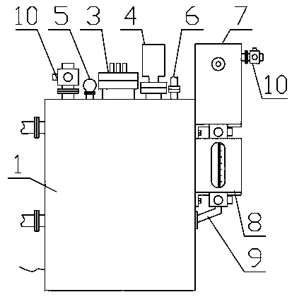
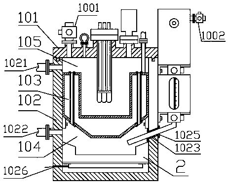
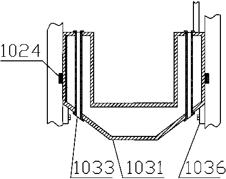

Image

  • Rare gas separation device and control method thereof
  • Rare gas separation device and control method thereof
  • Rare gas separation device and control method thereof

Examples


Embodiment Construction

[0031]In describing the present invention, it is to be understood that the terms "center", "upper", "lower", "front", "rear", "left", "right", "vertical", "horizontal", The orientations or positional relationships indicated by "top", "bottom", "inner", "outer", etc. are based on the orientations or positional relationships shown in the drawings, and are only for the convenience of describing the present invention and simplifying the description, rather than indicating or implying References to devices or elements must have a particular orientation, be constructed, and operate in a particular orientation and therefore should not be construed as limiting the invention. The terms "first" and "second" are used for descriptive purposes only, and cannot be understood as indicating or implying relative importance or implicitly specifying the quantity of indicated technical features. Thus, a feature defined as "first" and "second" may explicitly or implicitly include one or more of th...


PUM


Abstract

Belonging to the technical field of liquid-gas separation, the invention provides a rare gas separation device and a control method thereof. The separation device comprises a separation chamber, a heater, a purification apparatus, a liquid collection chamber, a liquid storage chamber and the like. The separation device provided by the invention can separate rare gas in liquid with high precision in a short time. In an early sampling process, a design scheme separating sampling from storage is adopted, and can effectively avoid the mixing of air, in the separation process, a novel cold trap structure can quickly filter out water vapor in gas, the disposed purification apparatus can eliminate active gas in mixed gas, and the purified rare gas can be directly measured through a flow meter anda mass spectrometer. The device is particularly suitable for separating and researching rare gas dissolved in underground water.

Description

technical field [0001] The invention belongs to the technical field of liquid-gas separation, and in particular relates to a rare gas separation device and a control method thereof. Background technique [0002] Groundwater is an important carrier of paleoclimate information. When atmospheric precipitation infiltrates and recharges groundwater, a large amount of current climate information is preserved. If these information can be effectively identified, past climate changes can be well distinguished. The solubility of rare gases in atmospheric precipitation changes with the change of temperature. During the rainfall process, rare gases enter the underground aquifer together with precipitation, so the concentration of rare gases in groundwater records the temperature when precipitation infiltrates and recharges groundwater. After nearly 50 years of development, this method has gradually become one of the important methods for paleoclimate research. It provides as much inform...

Claims


Application Information

Patent Timeline
IPC IPC(8): C02F1/20C02F1/04G01N1/34G01N1/40G01N27/62G01F1/00
CPCC02F1/20C02F1/04G01N1/34G01N1/4022G01N27/62G01F1/00G01N2001/4033
Inventor 吴耀华石进水王临潼赵倩
Owner SHANDONG TRANSPORT VOCATIONAL COLLEGE
Learn More