
Gas production and supercharging device

A technology of supercharging device and heating device, which is applied in jet propulsion device, gas turbine device, rocket engine device, etc., can solve the problems of low use efficiency of high-pressure gas, complicated pipeline, large occupied volume, etc., to reduce heating demand, The effect of increasing gas production and eliminating leakage

Active Publication Date: 2020-02-11
HUBEI INST OF AEROSPACE CHEMOTECH
View PDF13 Cites 0 Cited by
  • Summary
  • Abstract
  • Description
  • Claims
  • Application Information

AI Technical Summary

Problems solved by technology

[0002] In fuel-based aircraft engines, with the consumption of kerosene, the liquid level decreases, forming a certain vacuum area, and a certain pressure is required to continue the supply of fuel. Nowadays, the method of inflating high-pressure cylinders is commonly used, but the cylinders need Regular inspection, large volume, difficult maintenance of high-pressure gas, low efficiency of high-pressure gas without heating, increasing the weight of the system, and the introduction of a heating system increases the complexity of the system
[0003] The chemical gas-generating supercharger is generally ignited by a gas generator that uses sodium azide as the main gas-generating drug. The reaction only produces nitrogen, and the gas production rate is only 40% to 50%, and the reaction cannot be stopped after the start. Restricted conditions of use of the gas generator
[0004] In the prior art, gas cylinder pressurization is mostly used. The structure of gas cylinder pressurization is simple, but it is difficult to maintain. It must be equipped with a special site for protection. It is not suitable for high-mobility pressurization sites, and some use self-pressurization systems. Supercharging, complex structure, cooling operation of the introduced gas is required, and the pipeline is complicated

Method used


Image

  • Gas production and supercharging device
  • Gas production and supercharging device
  • Gas production and supercharging device

Examples


Embodiment 1

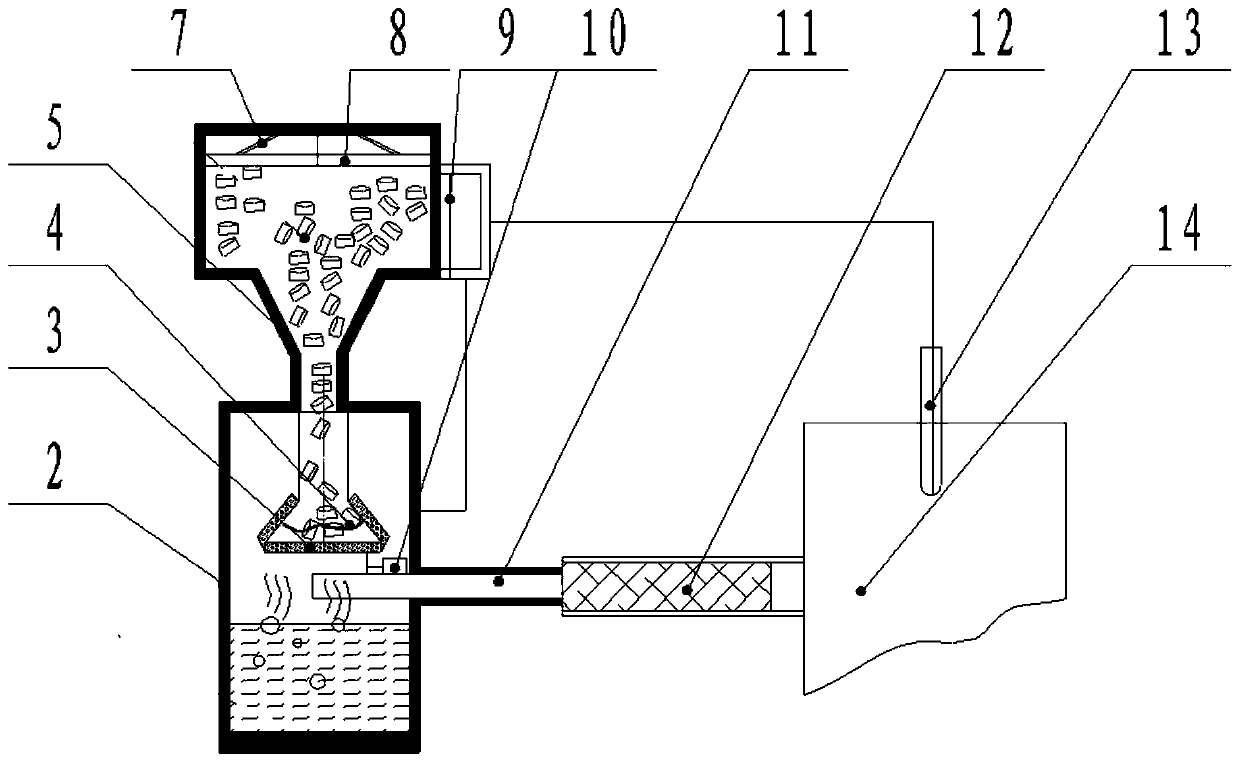
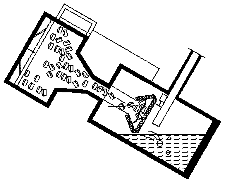
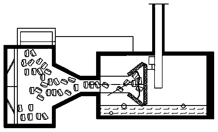
[0037] A gas production pressurization device, including a gas production module, a push module, a control module, and an adaptive attitude structure design, the specific structure of which is as follows figure 1 Shown:

[0038]Gas production module: a sealed tank body 2 with a heating device 4, a screen 3, a sodium azide gas generating agent, a vibration motor 10 and a certain amount of water; the tank body is divided into upper and lower parts, and the upper part is a feeding box 5 , is used to contain the gas generating agent, the lower end is a gas storage tank, which is used to store the reaction gas, and a certain amount of water is placed for the sodium azide heating product sodium to react again; the lower end neck of the funnel-shaped feeding box 5 extends into the storage tank In the gas box, the heating device 4, the screen 3 and the vibrating motor 10 are all arranged at the neck port of the lower end of the charging box 5, so that the gas generating agent is heate...


PUM


Abstract

The invention relates to a gas production and supercharging device which comprises a sealing tank (2), a gas outlet pipe (11), a supercharging container (14), a pressure sensor (13) and a microcomputer controller (9). A heating device (4) is arranged in the sealing tank (2) so as to heat a gas generation agent in the sealing tank (2). The gas outlet pipe (11) is connected with a gas outlet on theside wall of the sealing tank (2) and the supercharging container (14). The pressure sensor (13) is connected with the supercharging container (14) and the microcomputer controller (9) and is used formonitoring the pressure in the supercharging container (14) and transmitting pressure data to the microcomputer controller (9). The microcomputer controller (9) is connected with the heating device (4) in the sealing tank (2) and is used for comparing the received pressure data with a set pressure value to form a control command for controlling whether the heating device (4) works or not. The device is high in gas production efficiency and can be used for various fields needing gas supercharging.

Description

technical field [0001] The invention generally belongs to the field of controllable inflation technologies such as aircraft fuel tank pressurization and satellite cold air propulsion, and in particular relates to a gas generation pressurization device. Background technique [0002] In fuel-based aircraft engines, with the consumption of kerosene, the liquid level decreases, forming a certain vacuum area, and a certain pressure is required to continue the supply of fuel. Nowadays, the method of inflating high-pressure cylinders is commonly used, but the cylinders need Periodic testing takes up a large volume, and the use and maintenance of high-pressure gas is difficult. The use of high-pressure gas without heating is inefficient, which increases the weight of the system, and the introduction of a heating system increases the complexity of the system. [0003] The chemical gas-generating supercharger is generally ignited by a gas generator that uses sodium azide as the main g...

Claims


Application Information

Patent Timeline
IPC IPC(8): F02C6/20F02C7/22F02C9/26F02C9/28F02K9/50
CPCF02C6/20F02C7/22F02C9/26F02C9/28F02K9/50
Inventor 毛龙鲁国林杨威张文龙周渝淞姚俊
Owner HUBEI INST OF AEROSPACE CHEMOTECH
Learn More