
Laser scanning electrode structure and laser scanning control system

A technology of laser scanning and electrode structure, applied in the field of microelectronics and optics, can solve the problems of changing the refraction constant of liquid crystal, the scanning frequency is limited, and affecting the laser propagation path, etc., to achieve precise control, realize large-angle regulation, and increase the angle. The effect of control accuracy

Active Publication Date: 2020-02-11
SOUTH UNIVERSITY OF SCIENCE AND TECHNOLOGY OF CHINA +1
View PDF5 Cites 1 Cited by
  • Summary
  • Abstract
  • Description
  • Claims
  • Application Information

AI Technical Summary

Problems solved by technology

However, mechanical laser scanning devices have some defects, mainly manifested in two aspects, that is, the service life is short, and the scanning frequency is greatly limited by mechanical inertia
In order to improve these problems, it has been reported in the previous literature that by applying a voltage on the liquid crystal, the refractive constant of the liquid crystal is changed, thereby affecting the propagation path of the laser

Method used


Image

  • Laser scanning electrode structure and laser scanning control system
  • Laser scanning electrode structure and laser scanning control system
  • Laser scanning electrode structure and laser scanning control system

Examples


Embodiment 1

[0059] Example 1:

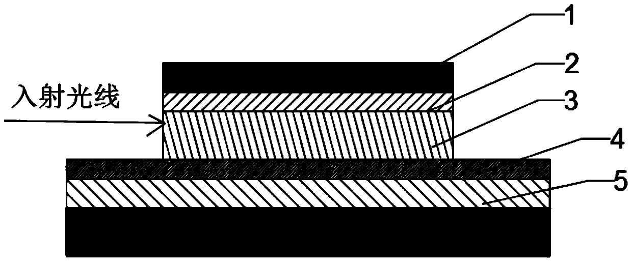
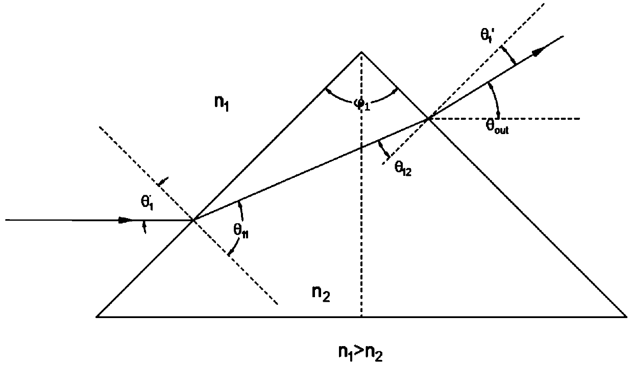
[0060] Such as figure 1 , figure 2 , a laser scanning electrode structure, comprising a liquid crystal layer 3, an electrode driving layer 2 is arranged above the liquid crystal layer 3, an electrode driving device is arranged on the electrode driving layer, and the electrode driving device includes a laser emission angle control part, the The laser emission angle control unit includes an incident side and an outgoing side, both of which are straight sides and intersect each other or their extension lines, and the electrode driving device is electrically connected to the liquid crystal layer. The base of the triangle formed by the intersection of the incident side and the outgoing side is parallel to the laser incident direction. The laser emission angle control part is configured as an isosceles triangle or an isosceles trapezoid, and the incident side and the emitting side are respectively configured as two waist sides of an isosceles triangle or an is...

Embodiment 2

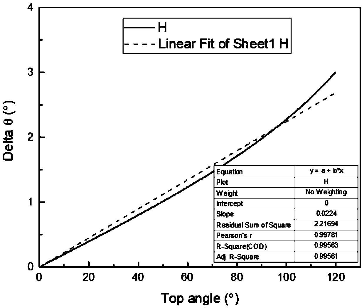
[0074] Such as Figure 4 , in embodiment 2, we can realize a laser deflection device for laser scanning up and down deflection by using this single laser scanning electrode structure combination, and isolate the ITO layer (electrode driving layer) above the liquid crystal layer into several mutually independent non-conductive regions (area S). The discrete electrodes can be roughly divided into U series of upper bias electrodes and D series of lower bias electrodes. Each level of electrodes is controlled independently of each other, and is numbered as the zeroth level electrode U from left to right. 0 , the first-stage electrode U 1 , the second electrode U 2 .....Wait. In order to better illustrate the effect of this embodiment, the upper deflection electrode U series and the lower deflection electrode D series are set in this embodiment, which can expand the laser scanning angle. In this embodiment, in order to facilitate the angle calculation, the upper and lower deflec...

Embodiment 3

[0080] In Embodiment 3, it is also possible to set different electrodes to deflect at different angles, such as setting a large-angle deflection as the main, and a small-angle deflection as a supplementary way, such as setting the front deflection angle to 5° deflection, and the small electrode at the back It is set to 3° deflection, and the most edge deflection angle is set to 2° or 1° deflection. Of course, different angles can also be selected in other embodiments. In this way, it is better than setting each laser deflection to the same angle. For the angle of deflection, different electrodes are selected for further regulation, but this is more computationally intensive.


PUM


Abstract

The invention provides a laser scanning electrode structure. The laser scanning electrode structure comprises a liquid crystal layer, an electrode driving layer is arranged above the liquid crystal layer, an electrode driving device is arranged on the electrode driving layer, the electrode driving device comprises a laser angle control part, the laser angle control part comprises an incident edgeand an emergent edge, the incident edge and the emergent edge are straight edges and are intersected with each other or extending lines of the incident edge and the emergent edge are intersected witheach other, and the electrode driving device is electrically connected with the liquid crystal layer. Through the arrangement of the liquid crystal layer and the electrode driving device, the refractive index of the liquid crystal layer can be changed through electrode control, and therefore, the change of the laser propagation direction is achieved. Because of the fact that a discrete electrode structure is adopted, when high sampling frequency and high-precision regulation and control are achieved, the requirement for later-period electric control signals is greatly lowered, and accurate control over the scanning angle by the voltage is achieved.

Description

technical field [0001] The invention relates to the fields of microelectronics and optics, in particular to a laser scanning electrode structure and a laser scanning control system. Background technique [0002] Laser scanning technology has a wide range of application prospects, such as virtual interactive systems, 3D scanning modeling, laser radar, and so on. At present, most laser scans achieve continuous laser scanning by mechanically rotating miniature mirrors. However, the mechanical laser scanning device has some defects, which are mainly manifested in two aspects, that is, the service life is short, and the scanning frequency is greatly limited by the mechanical inertia. In order to improve these problems, it has been reported in the previous literature that the use of voltage is applied to the liquid crystal to change the refractive constant of the liquid crystal, thereby affecting the propagation path of the laser. However, how to design this kind of liquid cryst...

Claims


Application Information

Patent Timeline
IPC IPC(8): G02F1/13G02F1/133G02F1/1343G02F1/29
CPCG02F1/13306G02F1/134309G02F1/1326G02F1/29
Inventor 邱成峰娄飞刘红均孙小卫程鑫刘召军庹勇
Owner SOUTH UNIVERSITY OF SCIENCE AND TECHNOLOGY OF CHINA
Learn More