Vertical type polishing grinder

A grinding machine and vertical technology, which is applied to surface polishing machine tools, grinding/polishing equipment, grinding machines, etc., can solve the problems of high cost of fixture replacement, poor polishing environment, and non-universal fixtures, etc., to achieve high work efficiency and save Replacing the abrasive and the time of the workpiece, the effect of the polishing effect is remarkable

Pending Publication Date: 2020-02-14
厦门东山盛机械有限公司
View PDF0 Cites 8 Cited by
  • Summary
  • Abstract
  • Description
  • Claims
  • Application Information

AI Technical Summary

Problems solved by technology

[0004] Manual polishing: the master can only take one workpiece at a time and grind it on the cloth wheel machine, and in the process of polishing, it needs to add polishing wax and other operations, which needs to be operated by a professional polishing master, and the polishing environment is relatively harsh, and the polishing effect is not good. stable, low efficiency
The common manual polishing process requires a polishing master and a polishing machine, and the labor cost is very high
[0005] Manipulator grinding: The manipulator grabs a workpiece, which is inefficient. Since a workpiece requires one to three different polishing processes, a robot needs to be equipped with three polishing machines to adapt to different workpiece polishing operations, and the manufacturing cost is extremely high; In the case of limited production capacity, multiple sets of equipment are required on the production site (each set of equipment is equipped with an industrial robot, two loading and unloading platforms, and one to three polishing machines). Universal use among devices, high cost and long time period for fixture replacement

Method used


Image

  • Vertical type polishing grinder
  • Vertical type polishing grinder
  • Vertical type polishing grinder

Examples


Embodiment Construction

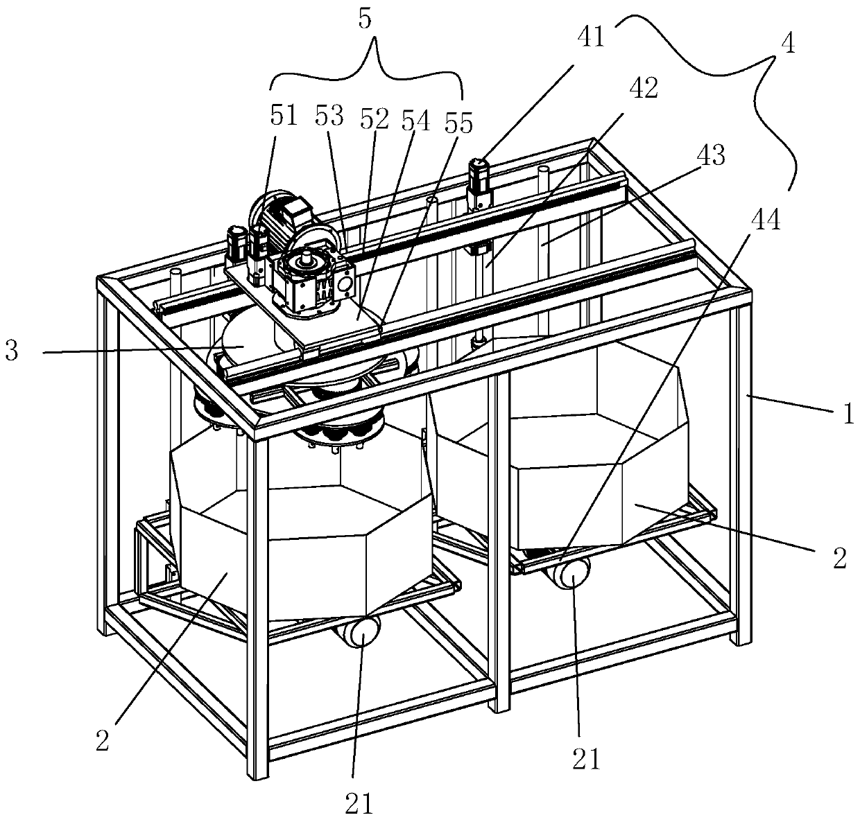
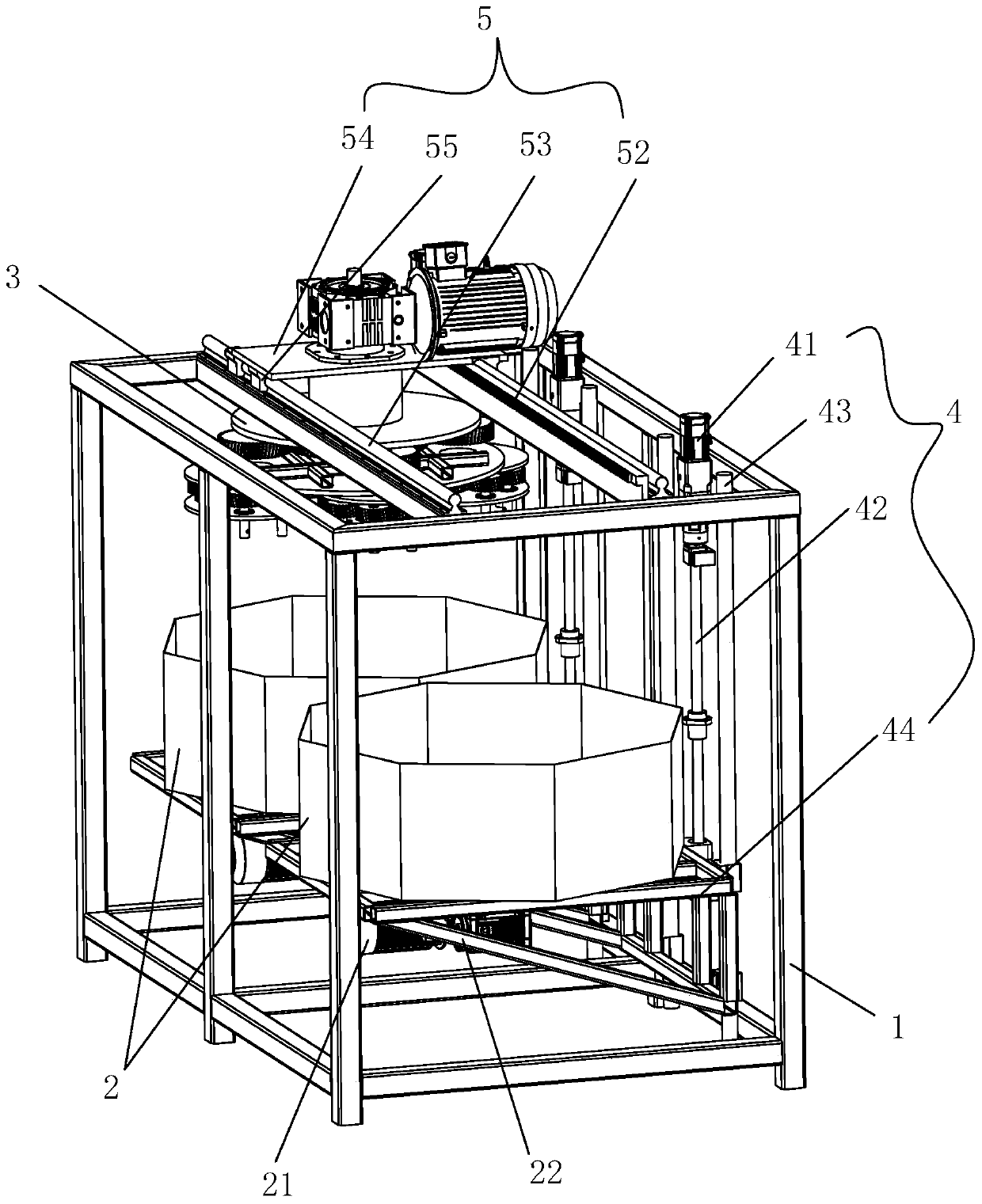
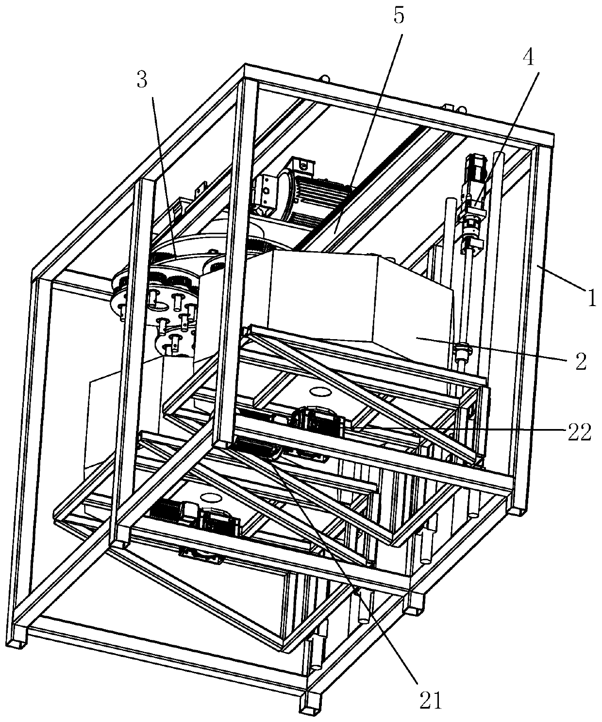
[0040] see Figure 1 to Figure 7As shown, the vertical polishing and grinding machine disclosed by the present invention includes a frame 1 , two abrasive drums 2 and a set of rotating mechanisms 3 . Two sets of lifting devices 4 are installed side by side on the side of the frame 1, and a set of translation device 5 is installed on the top surface of the frame 1. The two abrasive cylinders 2 are rotatably installed on two sets of lifting devices 4, and the lifting device 4 drives the abrasive cylinders 2 to move up and down. The two abrasive cylinders 2 are respectively filled with coarse and fine materials, which can be Grinding and fine grinding, realizing double-level processing, saving time for changing abrasives and workpieces, and further improving efficiency. The openings of the two abrasive cylinders 2 are upward, so that the abrasive cylinders 2 are vertical. An abrasive motor 21 and an abrasive reducer 22 are respectively installed at the bottom of each abrasive c...


PUM


Abstract

The invention discloses a vertical type polishing grinder. Two sets of lifting devices are arranged on the side surface of a rack side by side; a set of horizontally-moving device is arranged on the top surface of the rack; grinding material barrels are rotationally arranged on the lifting devices; openings of the grinding material barrels are vertical upwards; grinding material motors are transmitted to the grinding material barrels through grinding material reducers; a rotating mechanism is rotationally arranged on the horizontally-moving device; the rotating mechanism comprises a sun wheel,planet wheels and satellite wheels; a rotating motor is transmitted to a sun wheel shaft of the rotating mechanism to rotate through a rotating reducer; the sun wheel and a primary rotating disc arefixedly mounted on the sun wheel shaft; planet wheel shafts are rotationally mounted on the primary rotating disc; the planet wheels and a secondary rotating disc are fixedly mounted on the planet wheel shafts; the sun wheel is transmitted to the planet wheels; satellite wheel shafts are rotationally mounted on the secondary rotating disc; the satellite wheels are fixedly mounted on the satellitewheel shafts; and the planet wheels are transmitted to the satellite wheels to drive a tooling clamp to rotate. According to the vertical type polishing grinder, the structure is simple, the operate is easy, the working efficiency is high, the labor is saved, the universality is good, the polishing effect is stable, and the manufacturing cost is low.

Description

technical field [0001] The invention relates to a vertical polishing grinder. Background technique [0002] Grinding and polishing are processes for surface processing of objects in order to obtain the required size and better surface quality. [0003] Existing polishing and grinding are usually divided into manual grinding or mechanical grinding. [0004] Manual polishing: the master can only take one workpiece at a time and grind it on the cloth wheel machine, and in the process of polishing, it needs to add polishing wax and other operations, which needs to be operated by a professional polishing master, and the polishing environment is relatively harsh, and the polishing effect is not good. Stable, low efficiency. The common manual polishing process requires a polishing master and a polishing machine, and the labor cost is very high. [0005] Manipulator grinding: The manipulator grabs a workpiece, which is inefficient. Since one workpiece requires one to three differ...

Claims


Application Information

Patent Timeline
Patent Type & Authority Applications(China)
IPC IPC(8): B24B31/033B24B31/12
CPCB24B31/003B24B31/033B24B31/12
Inventor 赵国英
Owner 厦门东山盛机械有限公司
Why Eureka
Try Eureka