
Spray quenching device with rotating effect and using method thereof

A technology of quenching device and spraying device, which is applied in the field of quenching, can solve the problems of uneven quenching and many unqualified workpieces, achieve uniform quenching, improve product qualification rate, and ensure the effect of product qualification rate

Inactive Publication Date: 2020-02-18
HENGYANG HONGYU MACHINERY MANFUACTURING CO LTD
View PDF6 Cites 3 Cited by
  • Summary
  • Abstract
  • Description
  • Claims
  • Application Information

AI Technical Summary

Problems solved by technology

[0004] The purpose of the present invention is to provide a spray quenching device with a rotating effect and its use method to solve the problems of uneven quenching and many unqualified workpieces in the above background technology

Method used


Image

  • Spray quenching device with rotating effect and using method thereof
  • Spray quenching device with rotating effect and using method thereof
  • Spray quenching device with rotating effect and using method thereof

Examples


Embodiment 1

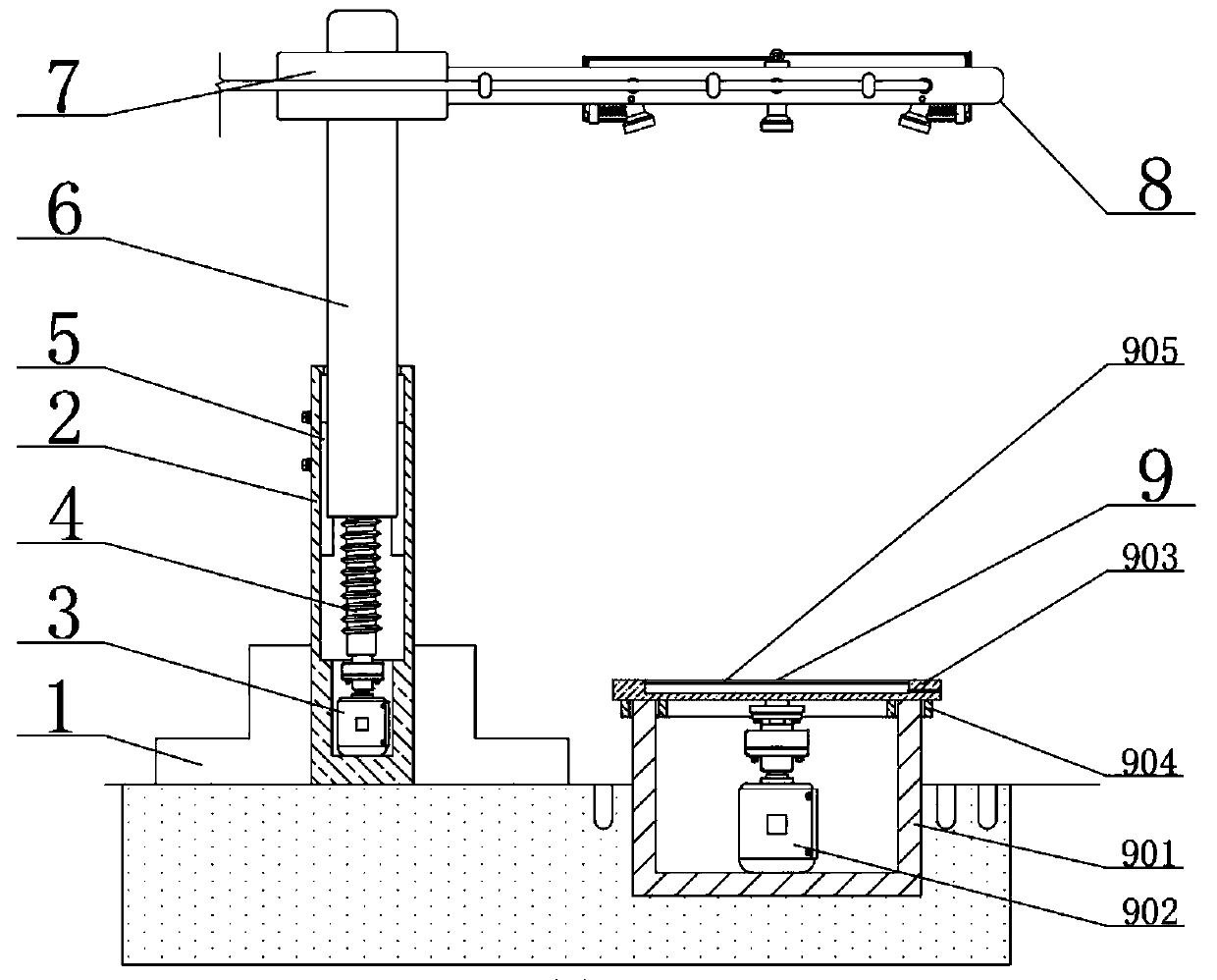
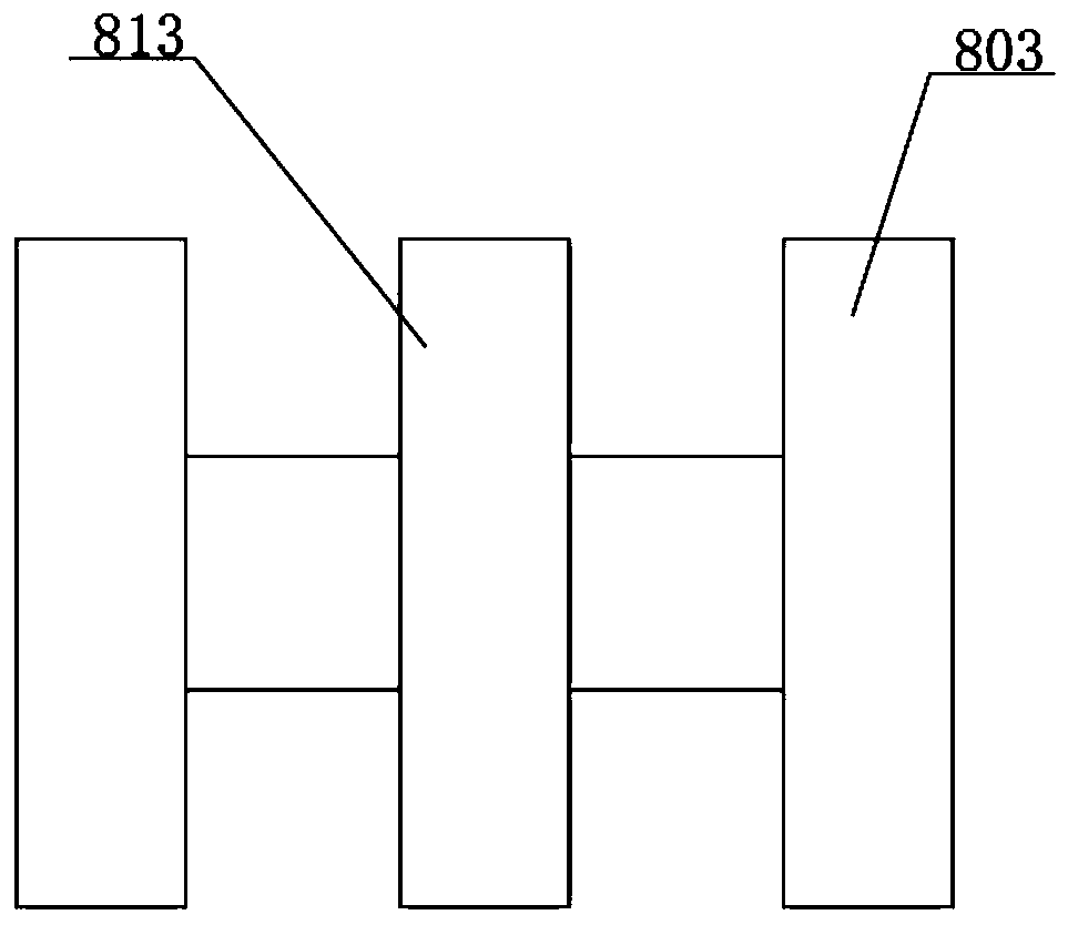
[0029] see Figure 1-Figure 4 , the present invention provides a technical solution:

[0030]A spray quenching device with rotation effect and its use method, comprising a fixed base 1 and a fixed cylinder 2, the fixed base 1 is fixedly connected with the fixed cylinder 2 inside, the lower end surface of the fixed cylinder 2 is fixedly connected with the rotating motor 3 inside, and the rotating motor 3 The end of the main shaft is fixedly connected with the threaded rod 4, and the outer side of the threaded rod 4 is spirally connected with the lifting rod 6, and the left and right sides of the lifting rod 6 are provided with grooves, and the lifting rod 6 is slidingly connected with the limit plate 5 through the groove, and the lifting rod The outer side of 6 is slidingly connected with the fixed cylinder 2. This setting ensures that the lifting rod 6 can only move up and down, avoids its own rotation, and ensures the normal spraying work of the spraying device 8. The upper s...

Embodiment 2

[0040] see figure 1 , figure 2 , image 3 and Figure 4 , the present invention provides a technical solution:

[0041] A spray quenching device with rotation effect and its use method, comprising a fixed base 1 and a fixed cylinder 2, the fixed base 1 is fixedly connected with the fixed cylinder 2 inside, the lower end surface of the fixed cylinder 2 is fixedly connected with the rotating motor 3 inside, and the rotating motor 3 The end of the main shaft is fixedly connected with the threaded rod 4, and the outer side of the threaded rod 4 is spirally connected with the lifting rod 6, and the left and right sides of the lifting rod 6 are provided with grooves, and the lifting rod 6 is slidingly connected with the limit plate 5 through the groove, and the lifting rod The outer side of 6 is slidingly connected with the fixed cylinder 2. This setting ensures that the lifting rod 6 can only move up and down, avoids its own rotation, and ensures the normal spraying work of the...


PUM


Abstract

The invention relates to the technical field of quenching, and particularly relates to a spray quenching device with a rotating effect and a using method thereof. The spray quenching device comprisesa fixed base and a fixed cylinder, wherein the fixed cylinder is fixedly connected to the interior of the fixed base; a rotating motor is fixedly connected to the interior of the lower end surface ofthe fixed cylinder; a threaded rod is fixedly connected to the tail end of a main shaft of the rotating motor; a lifting rod is spirally connected to the outer side of the threaded rod; a fixing ringis fixedly connected to the upper part of the outer side of the lifting rod; a spraying device is fixedly connected to the right end surface of the fixing ring; the spraying device comprises a fixingrod and a pay-off motor; and the left end surface of the fixing rod is fixedly connected with the fixing ring. According to the spray quenching device, the fixing rod, a side water mist spray head anda central water mist spray head are arranged, and a connecting line is driven to move through the rotation of the rotating motor, so that the angle of the side water mist spray head is adjusted, workpieces with different sizes can be rapidly cooled, the workpieces can be comprehensively quenched, the product quality is guaranteed, and the product percent of pass is improved.

Description

technical field [0001] The invention relates to the technical field of quenching, in particular to a spray quenching device with a rotating effect and a use method thereof. Background technique [0002] The quenching of steel is to heat the steel to a temperature above the critical temperature Ac3 or Ac1, keep it warm for a period of time to make it fully or partially austenitized, and then quickly cool it to below Ms at a cooling rate greater than the critical cooling rate for martensitic transformation Heat treatment process, usually the solution treatment of aluminum alloy, copper alloy, titanium alloy, tempered glass and other materials or the heat treatment process with rapid cooling process is called quenching, and then tempered with different temperatures to greatly improve the steel Rigidity, hardness, wear resistance, fatigue strength and toughness, etc., so as to meet the different use requirements of various mechanical parts and tools, and can also meet the specia...

Claims


Application Information

Patent Timeline
Patent Type & Authority Applications(China)
IPC IPC(8): C21D1/667C21D1/18
CPCC21D1/18C21D1/667
Inventor 何云辉彭俊
Owner HENGYANG HONGYU MACHINERY MANFUACTURING CO LTD
Learn More