Wireless power transmission topology with strong anti-offset performance based on multi-frequency energy parallel transmission

A technology of wireless power transmission and anti-offset, applied in the direction of electrical components, circuit devices, etc., can solve the problems of complex output characteristics of combined converters, difficult parameter design, large copper consumption, etc., to save materials, avoid mutual influence, The effect of reducing size and weight

Pending Publication Date: 2020-02-18
NANJING UNIV OF AERONAUTICS & ASTRONAUTICS +1
View PDF1 Cites 11 Cited by
  • Summary
  • Abstract
  • Description
  • Claims
  • Application Information

AI Technical Summary

Problems solved by technology

However, the existing technical solutions for improving the dislocation tolerance of the combined output require two sets of transformer windings, which consume a large amount of copper and are expensive; and the external characteristics are limited by the structure of the non-contact transformer, and complex dislocations such as angular and diagonal lines Under working conditions, the magnetic flux coupling between the primary and secondary sides cannot be ignored, which leads to complex output characteristics of the combined converter and difficult parameter design, and stable output can only be obtained in certain specific offset directions

Method used


Image

  • Wireless power transmission topology with strong anti-offset performance based on multi-frequency energy parallel transmission
  • Wireless power transmission topology with strong anti-offset performance based on multi-frequency energy parallel transmission
  • Wireless power transmission topology with strong anti-offset performance based on multi-frequency energy parallel transmission

Examples


Embodiment Construction

[0076] The present invention will be further explained below in conjunction with the accompanying drawings.

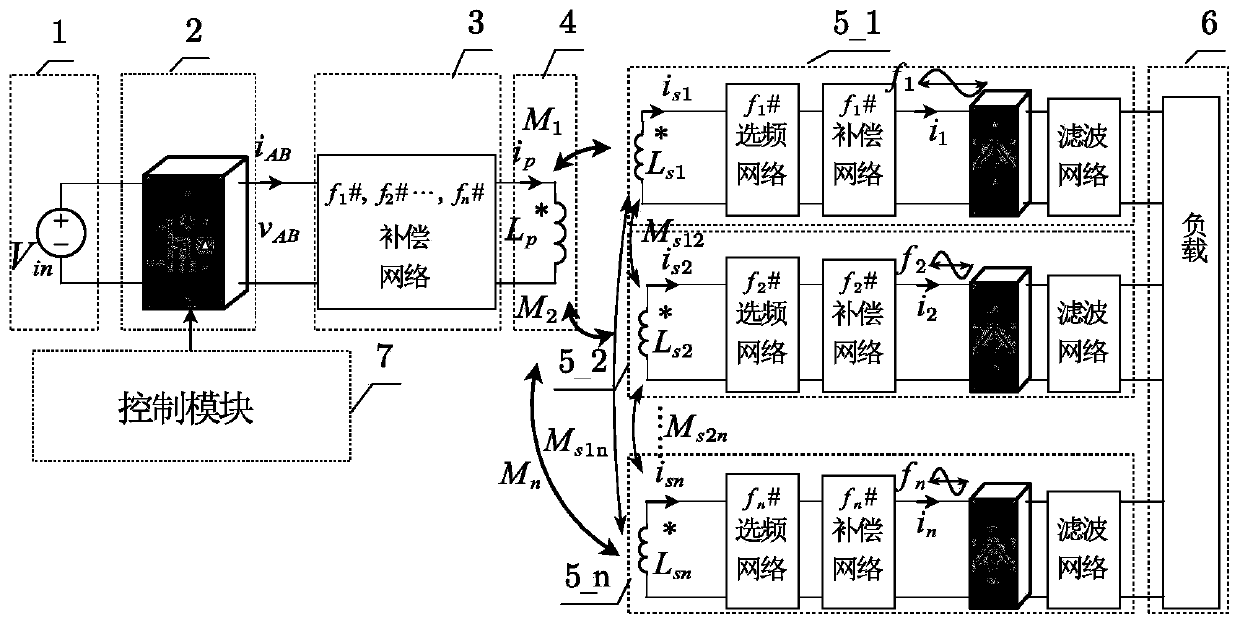
[0077] The present invention proposes a wireless power transmission topology with strong anti-offset performance based on parallel transmission of multi-frequency energy, which is suitable for different types of magnetic coupling mechanisms and winding forms (such as circular, square, DD-shaped and rail-shaped, etc.), aiming at In realizing the decoupling control of multi-frequency energy, avoiding the influence of cross-coupling, and improving the dislocation tolerance of the wireless power transmission system.

[0078] figure 1 The basic circuit composition form of the wireless power transmission topology based on multi-frequency energy parallel transmission of the present invention is given. The system structure includes a DC power supply 1, a high-frequency inverter 2, a primary-side multi-frequency shared compensation network 3, and a primary-side transmitting Co...


PUM


Abstract

The invention discloses a wireless power transmission topology with strong anti-offset performance based on multi-frequency energy parallel transmission. A control module outputs a drive square wave signal of a high-frequency inverter, so that the output voltage of the high-frequency inverter is the mixed superposition of double-frequency or multi-frequency voltages. After through a primary side multi-frequency shared compensation network, double-frequency or multi-frequency current simultaneously excites a primary side transmitting coil, multi-frequency energy is transmitted to a receiving module in parallel through magnetic field coupling, the receiving module achieves double-frequency or multi-frequency energy separation and decoupling transmission, alternating-current voltage or current with the frequency being each frequency is outputted, and the alternating-current voltage or current is outputted to a load for power supply in a combined mode after being rectified and filtered respectively. Due to the design of resonance parameters, the output under different frequencies is inconsistent with the change trend of mutual inductance; after combined output, output voltage or current insensitive to mutual inductance change is obtained, output fluctuation caused by change of the relative positions of the transmitting coil and the receiving coil is greatly reduced, and stable output of the wireless power transmission system under the high-offset working condition is guaranteed.

Description

technical field [0001] The invention relates to a wireless power transmission topology with strong anti-offset performance, which belongs to the field of power conversion. Background technique [0002] Inductive wireless power transmission uses magnetic field coupling to realize "wireless power supply", that is, a non-contact transformer with completely separated primary and secondary sides is used to transmit electric energy through high-frequency magnetic field coupling, so that the primary side (power supply side) and secondary side ( consumption side) without physical connection. Compared with the traditional contact power supply, non-contact power supply is convenient and safe to use, without sparks and electric shock hazards, without dust accumulation and contact loss, without mechanical wear and corresponding maintenance problems, and can adapt to a variety of severe weather and environments, and is easy to realize Automatic power supply has wide application prospect...

Claims


Application Information

Patent Timeline
IPC IPC(8): H02J50/12H02J50/70
CPCH02J50/12H02J50/70
Inventor 柯光洁陈乾宏徐立刚温振霖任小永张之梁
Owner NANJING UNIV OF AERONAUTICS & ASTRONAUTICS
Why Eureka
Try Eureka