Novel plate shearing machine with flat cutting surface
What is Al technical title?
Al technical title is built by PatSnap Al team. It summarizes the technical point description of the patent document.
A cutting surface and shearing machine technology, which is applied to shearing devices, shearing machine equipment, accessories of shearing machines, etc. Good cutting effect, avoid scratches, smooth cutting surface
Inactive Publication Date: 2020-02-21
阮健宁
View PDF0 Cites 4 Cited by
Summary
Abstract
Description
Claims
Application Information
AI Technical Summary
This helps you quickly interpret patents by identifying the three key elements:
Problems solved by technology
Method used
Benefits of technology
Problems solved by technology
[0002] The plate shearing machine is a machine that uses one blade to make a reciprocating linear motion relative to the other blade to cut the plate. It uses the moving blade and the fixed plate to apply shear force to metal plates of various thicknesses with a reasonable blade gap. The plate is broken and separated according to the required size. The shearing machine is a kind of forging machinery. Its main function is the metal processing industry. Decoration and other industries provide the required special machinery and complete sets of equipment. The existing shears are huge in size and complicated to operate. When in use, multiple people are required to operate, and when cutting, due to the excessive hardness of some metal plates, cutting The contact between the knife and the metal plate lacks a certain lubricating substance, which will easily cause the cutting knife to curl up, and when the material is loaded, the flatness of the metal plate is not enough, and it is easy to cause the cutting knife to collapse. Therefore, a cutting surface is designed. A flat new shearing machine is necessary
Method used
Image
Click on the blue label to locate the original text in one second.
Reading with bidirectional positioning of images and text.
Examples
Embodiment Construction
[0015] The following will clearly and completely describe the technical solutions in the embodiments of the present invention with reference to the accompanying drawings in the embodiments of the present invention. Obviously, the described embodiments are only some, not all, embodiments of the present invention. Based on the embodiments of the present invention, all other embodiments obtained by persons of ordinary skill in the art without making creative efforts belong to the protection scope of the present invention.
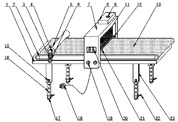
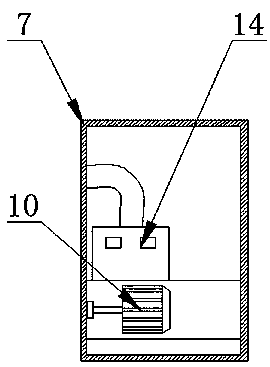
[0016] see Figure 1-2 , the present invention provides a technical solution: a new shearing machine with a flat cutting surface, including a frame 1, a conveyor 2, a movable pin 3, a bearing 4, a roller 5, a moving frame 6, a cutting table 7, and an oil tank 8 , liquid injection port 9, drive motor 10, cutter 11, liquid outlet 12, shear plate 13, vacuum cleaner 14, positioning bolt 15, positioning hole 16, universal wheel 17, external plug 18, fastening bolt ...
PUM
Abstract
The invention discloses a novel plate shearing machine with a flat cutting surface. The novel plate shearing machine comprises a rack, a conveyor, a movable pin, a bearing, a roller, a movable frame,a cutting table, an oil liquid box, a liquid injection port, a driving motor, a cutter, a liquid outlet, a shearing plate, a dust suction machine, a positioning bolt, a positioning hole, universal wheels, an external plug, a fastening bolt, a control panel, a dust removal plate, a stop plate and a supporting frame, wherein the conveyor is arranged at the top of the rack; the shearing plate is arranged at the top of the conveyor; the movable frame is arranged on one side of the shearing plate; the bearing is arranged at the top of the movable frame; the roller is arranged on one side of the bearing; the cutting table is arranged on one side of the roller; the oil liquid box is arranged at the top of the cutting table; the liquid injection port is formed in the top of the oil liquid box; thecutter is arranged on one side of the cutting table; and the dust removal plate is arranged on one side of the cutter. The plate shearing machine is simple to operate, the cutting surface is flat, the cutting effect is good, and the use convenience is greatly improved.
Description
technical field [0001] The invention relates to the technical field of shearing machines, in particular to a novel shearing machine with a smooth cutting surface. Background technique [0002] The plate shearing machine is a machine that uses one blade to make a reciprocating linear motion relative to the other blade to cut the plate. It uses the moving blade and the fixed plate to apply shear force to metal plates of various thicknesses with a reasonable blade gap. The plate is broken and separated according to the required size. The shearing machine is a kind of forging machinery. Its main function is the metal processing industry. Decoration and other industries provide the required special machinery and complete sets of equipment. The existing shears are huge in size and complicated to operate. When in use, multiple people are required to operate, and when cutting, due to the excessive hardness of some metal plates, cutting The contact between the knife and the metal pl...
Claims
Application Information
Patent Timeline
Application Date:The date an application was filed.
Publication Date:The date a patent or application was officially published.
First Publication Date:The earliest publication date of a patent with the same application number.
Issue Date:Publication date of the patent grant document.
PCT Entry Date:The Entry date of PCT National Phase.
Estimated Expiry Date:The statutory expiry date of a patent right according to the Patent Law, and it is the longest term of protection that the patent right can achieve without the termination of the patent right due to other reasons(Term extension factor has been taken into account ).
Invalid Date:Actual expiry date is based on effective date or publication date of legal transaction data of invalid patent.