
Coil-type equipment oil leakage plugging device and method

A plugging device and equipment technology, applied in the direction of mechanical equipment, engine sealing, engine components, etc., can solve the problems of reduced plugging capacity, increased equipment operation and maintenance costs, and reduced plugging success rate to meet the speed and sealing requirements High demand, improve long-term effectiveness, improve the effect of plugging effect

Active Publication Date: 2020-02-21
ELECTRIC POWER RESEARCH INSTITUTE OF STATE GRID SHANDONG ELECTRIC POWER COMPANY +3
View PDF3 Cites 1 Cited by
  • Summary
  • Abstract
  • Description
  • Claims
  • Application Information

AI Technical Summary

Problems solved by technology

In actual operation, due to the influence of manufacturing quality, operation and maintenance management, service environment, etc., oil leakage often occurs. Such problems can affect the appearance of the equipment and increase the cost of equipment operation and maintenance. safety; therefore, the treatment of oil leakage from coil equipment has become an important task for the operation and maintenance management of substation equipment; and the conventional treatment method is to pump out the insulating oil and then repair the damaged parts, such as bushings and flanges. After replacement, the insulating oil is purified and then injected into the transformer. The maintenance process generally takes a long period, and requires high manpower and material costs, which is difficult to meet the current maintenance efficiency requirements; and the glued on-line plugging technology is used , It has obvious advantages to complete the oil leakage plugging of the transformer equipment without power off. This technical method will not affect the normal operation of the equipment. Generally, the local defects of the oil leakage equipment are repaired, so the cost is low. If the material and process are selected reasonably, the equipment after plugging can meet the requirements of long-term service
[0003] The inventor found that although the glued on-line plugging technology can overcome the problems caused by power outage maintenance, it also has inconvenience during the plugging process. , so that the adhesive repair agent will be polluted by the leaked insulating oil, which will lead to a decrease in its sealing ability and reduce the success rate of sealing; at present, some other sealing methods, such as filling the oil leakage gap through plasticine, Apply adhesive repair agent on the outside of the plasticine and the oil leak to isolate the insulating oil to prevent the insulating oil from polluting the adhesive repair agent. However, it is difficult to completely fill the oil leakage gap by the sealing of the plasticine, and it is still unable to achieve a good anti-corrosion effect. Pollution effect; and by sticking the outer wall of the equipment to form an isolation area to accommodate the oil leakage gap and increase the pressure to be equal to the internal pressure of the equipment for sealing, it is necessary to accurately adjust the air pressure to achieve isolation, which is difficult to meet the high efficiency requirements during emergency repairs

Method used


Image

  • Coil-type equipment oil leakage plugging device and method
  • Coil-type equipment oil leakage plugging device and method

Examples


Embodiment 1

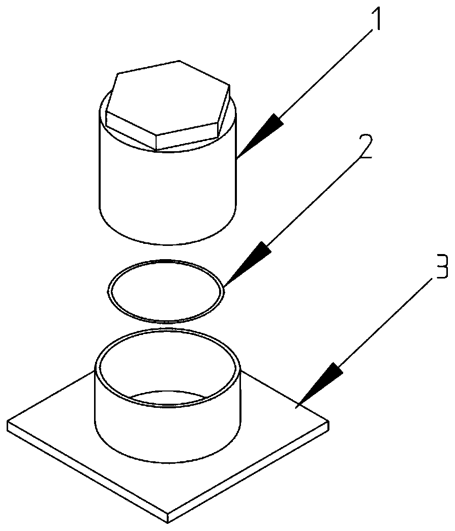
[0035] In a typical implementation of the present application, such as figure 1 As shown, a device and method for oil leakage plugging of coil type equipment applied to the outer wall of a planar workpiece are proposed.

[0036]The blocking device mainly includes three parts, a docking base, a gasket and a fastener. In this embodiment, the docking base is a bonding base 3 provided with a through hole and a docking cylinder communicating with the through hole. The bonding base is a planar plate, which is used to fit the planar outer wall of the workpiece to be blocked. The butt joint is arranged coaxially with the through hole and fixed on the joint base through the end. The joint joint and the fastener To cooperate, an annular gasket is provided between the fastener and the outer wall of the workpiece to be blocked. In this embodiment, the fastener is selected from a cylindrical fastening bolt cap 1 with one end closed, which has a A cavity, after cooperating with the bonding...

Embodiment 2

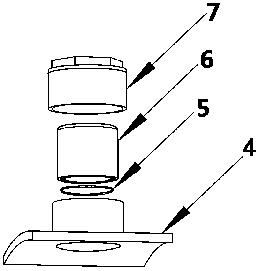
[0048] In a typical implementation of the present application, such as figure 2 As shown, a device and method for oil leakage plugging of coil type equipment applied to the outer wall of arc-shaped workpieces is proposed.

[0049] The difference from Embodiment 1 is that in this embodiment, the bonding base 4 is an arc-shaped plate, and while the sealing ring 5 is arranged between the fastening bolt cap 7 and the outer wall of the workpiece, a sleeve 6 is also added as a The middle fastener, the fastening bolt cap is a cylindrical structure with one end blocked, and a sleeve is fitted inside, one end of the sleeve contacts the fastening bolt cap, and the other end fits the sealing ring, and the fastening bolt cap Press the sealing ring through the sleeve to make the sealing ring close to the outer wall of the workpiece;

[0050] Further, one end of the sleeve fitting the gasket is an arc-shaped structure matching the outer wall of the workpiece to be sealed, which is used to...


PUM


Abstract

The invention discloses a coil-type equipment oil leakage plugging device and method. The coil-type equipment oil leakage plugging device includes a docking base, the docking base is provided with a through hole and a docking cylinder communicating with the through hole, the docking cylinder and the through hole are coaxial, the docking cylinder is fixed to a docking base through the end, the side, far away from the docking cylinder, of the docking base is used for being attached to the outer wall of a to-be-plugged workpiece, a fastening piece is arranged on the docking cylinder in a matchedmanner, a ring-shaped gasket is arranged between the fastening piece and the outer wall of the to-be-plugged workpiece, the fastening piece cooperates with the docking cylinder to press the gasket tothe periphery of the leakage position, and therefore discharged insulating oil can be drawn out into the fastening piece, the leaked insulating oil is prevented from flowing out from a gap between thedocking base and the outer wall, pollution to a binder applied to the exterior is avoided, the good solidification and sealing performance of the binder is ensured, and the efficiency and the sealingeffect of entire hinge on-line plugging are effectively improved.

Description

technical field [0001] This application relates to the field of electrical maintenance, in particular to a device and method for oil leakage plugging of coil equipment. Background technique [0002] Power grid coil equipment, such as transformers and reactors, often use oil medium to achieve insulation and cooling functions. In actual operation, due to the influence of manufacturing quality, operation and maintenance management, service environment, etc., oil leakage often occurs. Such problems can affect the appearance of the equipment and increase the cost of equipment operation and maintenance. safety; therefore, the treatment of oil leakage from coil equipment has become an important task for the operation and maintenance management of substation equipment; and the conventional treatment method is to pump out the insulating oil and then repair the damaged parts, such as bushings and flanges. After replacement, the insulating oil is purified and then injected into the tr...

Claims


Application Information

Patent Timeline
IPC IPC(8): F16J15/06
CPCF16J15/061
Inventor 杜宝帅索帅张忠文邓化凌乔亚霞张浩李新梅罗宏建步衍江李文谢清宽
Owner ELECTRIC POWER RESEARCH INSTITUTE OF STATE GRID SHANDONG ELECTRIC POWER COMPANY
Features
  • Generate Ideas
  • Intellectual Property
  • Life Sciences
  • Materials
  • Tech Scout
  • Unparalleled Data Quality
  • Higher Quality Content
  • 60% Fewer Hallucinations
Learn More