Micro-channel vapor chamber with recess structure

A micro-channel and vapor chamber technology, which is applied to electrical components, electric solid devices, circuits, etc., can solve the problem of increased heat transfer resistance of micro-channel condensing plates, preventing direct contact between steam and condensing plates, and the overall heat dissipation performance of the vapor chamber To achieve the effects of superior anti-drying characteristics, improved average temperature and heat dissipation performance, and improved steam convective heat transfer coefficient

Pending Publication Date: 2020-02-21
GUANGZHOU INTELLIGENT COOLING ENERGY SAVING TECH CO LTD
View PDF0 Cites 2 Cited by
  • Summary
  • Abstract
  • Description
  • Claims
  • Application Information

AI Technical Summary

Problems solved by technology

[0005] However, the structure of the current micro-channel liquid-absorbing core is relatively simple, and most of them are straight channel array structures.
Straight channel array structure liquid-absorbing core, the inner surface is smooth and gentle, when the steam is condensed on the inner surface of the channel, it is easy to form a layer of liquid film on the surface, which hinders the direct contact between the steam and the condensing plate, which leads to the transmission of the micro-channel condensing plate Thermal resistance increases, heat transfer capacity decreases
In addition, when the steam is cooled to form liquid droplets on the inner surface of the channel, because the inner surface of the straight channel is flat and subjected to high surface tension, it is not easy to drip and flow back to the evaporation end, thereby reducing the drying limit of the vapor chamber and making the vapor chamber Reduced overall thermal performance

Method used


Image

  • Micro-channel vapor chamber with recess structure
  • Micro-channel vapor chamber with recess structure
  • Micro-channel vapor chamber with recess structure

Examples


Embodiment 1

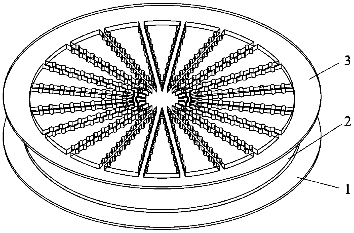
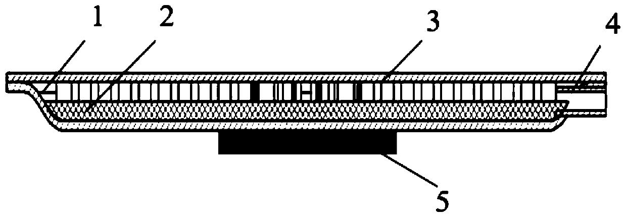
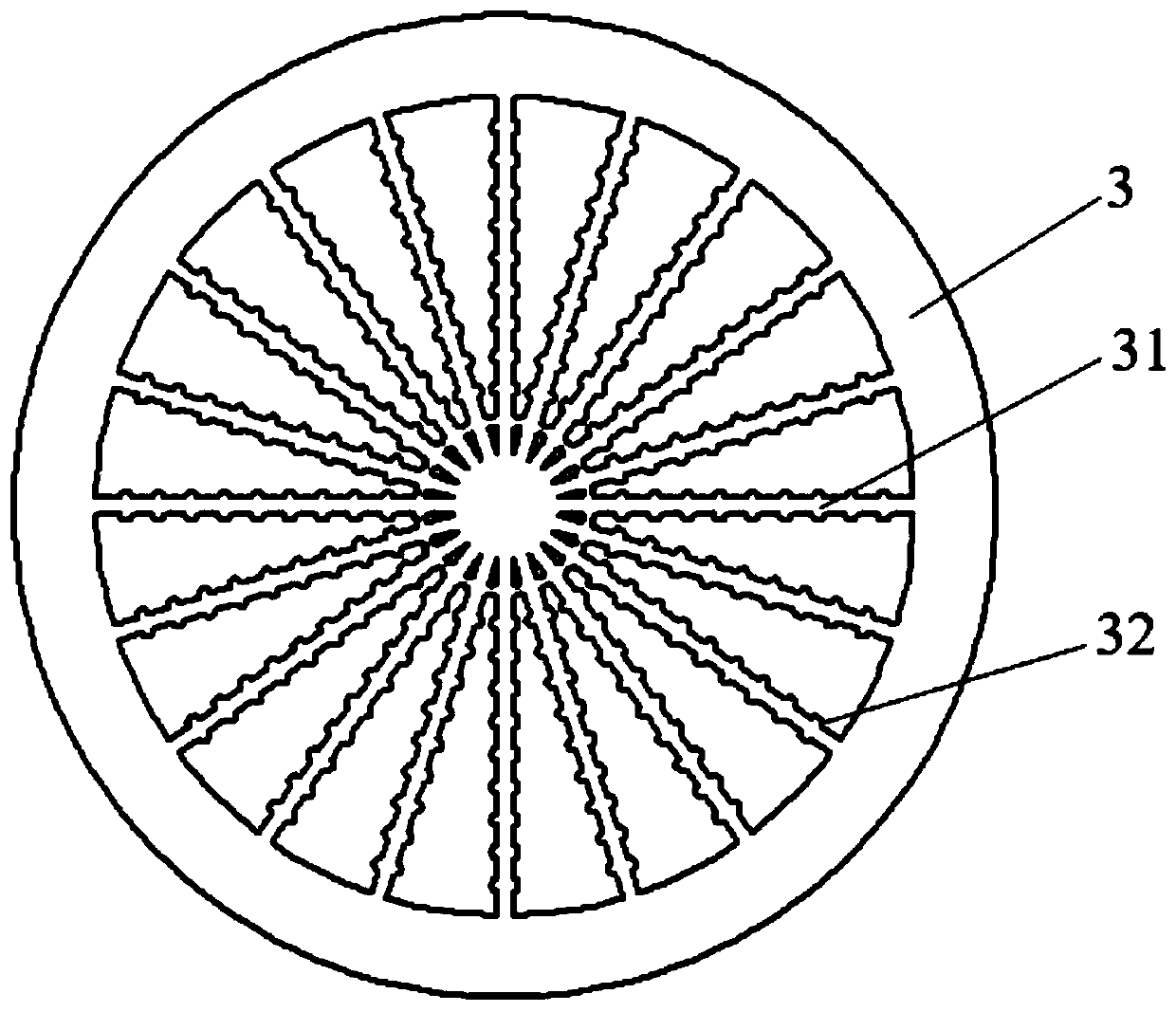
[0033] like Figure 1-Figure 3 As shown, a microchannel vapor chamber with a cavity structure includes a base plate 1, a capillary core 2 and a cover plate 3. A cavity is provided on the inner surface of the base plate, and the capillary core 2 is embedded in the cavity of the base plate to form a uniform vapor chamber. Evaporating end of the hot plate. In this embodiment, both the cover plate and the bottom plate are circular, and the inner surface of the cover plate is processed with a microchannel structure 31 in a circumferential array. Diverge toward the edge and arrange evenly. In this embodiment, there are 20 microchannels, and recess structures 32 are processed on both sides of the inner surface of the microchannels.

[0034] like image 3 As shown, in the present embodiment, the recess structure is made of a plurality of semicircular recesses 32, and a plurality of semicircular recesses are symmetrically distributed on both sides of the microchannel, and the diamete...

Embodiment 2

[0040] see Figure 4 and Figure 5 , The difference between this embodiment and Embodiment 1 is that the shape of the cover plate and the bottom plate is square, the microchannel array on the cover plate is a parallel rectangular straight microchannel array, and the cavity structure is a rectangular cavity.

[0041] Other parameter settings and processing methods of this embodiment are the same as those of Embodiment 1.

[0042] Image 6 Among them, Temperature represents temperature, and 340, 342, 344, etc. represent changes in temperature. Figure 7 Among them, Velocity represents the flow velocity.


PUM


Abstract

The invention discloses a micro-channel vapor chamber with a recess structure. The micro-channel vapor chamber comprises a bottom plate, a capillary core and a cover plate, a concave cavity is formedin the upper surface of the bottom plate, the capillary core is arranged in the concave cavity, a micro-channel structure is machined on the upper surface of the cover plate, concave cavity structuresare arranged on the two sides of the inner surface of the micro-channel structure, the bottom plate and the cover plate form a closed cavity in a welding mode, and the micro-channel vapor chamber with the concave cavity structures is formed through vacuumizing liquid injection. The micro-channel array with the concave cavity structure is adopted to replace a conventional condensation end liquid suction core structure, so that transmission and uniform distribution of a working medium are facilitated, the condensation area of the working medium is increased, a condensation backflow path is shortened, and lower flow resistance and excellent dryout resistance are achieved; and the concave cavity structure can increase the heat transfer area, can generate a jet throttling effect, can disturb steam flow, can inhibit formation of a condensate film, can promote condensation reflux and can increase the anti-dryout limit, so that the heat transfer efficiency is improved.

Description

technical field [0001] The invention relates to the technical field of heat dissipation of microelectronic devices and chips, in particular to a microchannel soaking plate with a cavity structure. Background technique [0002] With the miniaturization, integration and functional complexity of electronic equipment, the heating power of electronic chips is getting higher and higher. At present, the surface average heat flux density of electronic chips has exceeded 100W / cm 2 , and has a continuous increasing trend. At the same time, high heat flux will form "hot spots" on the surface of electronic devices, resulting in a decrease in the performance and reliability of electronic chips. [0003] The vapor chamber is a heat dissipation component that transfers heat through phase change. It can quickly transfer and diffuse the heat flow gathered on the surface of electronic components to the condensation surface for heat dissipation, thereby effectively reducing the surface heat ...

Claims


Application Information

Patent Timeline
Patent Type & Authority Applications(China)
IPC IPC(8): H01L23/427H01L23/367
CPCH01L23/367H01L23/427
Inventor 潘敏强黄平南陈阳刘庆云
Owner GUANGZHOU INTELLIGENT COOLING ENERGY SAVING TECH CO LTD
Why Eureka
Try Eureka