Composite heat dissipation water-cooling-free laser

A laser, no water cooling technology, applied in the field of lasers, can solve the problems of difficult to grasp the temperature control accuracy, heavy weight, short service life, etc., to achieve the effect of satisfying the portable performance, high degree of automation, and low heat dissipation requirements

Pending Publication Date: 2020-02-21
长沙大科光剑科技有限公司
View PDF0 Cites 1 Cited by
  • Summary
  • Abstract
  • Description
  • Claims
  • Application Information

AI Technical Summary

Problems solved by technology

[0003] In the existing water-free fiber lasers, the laser diode often has a phenomenon that the wavelength drifts with the change of temperature due to problems such as insufficient heat dissipation and waste heat enrichment, so that the central wavelength does not match the main absorption peak of the gain medium, resulting in a decrease in absorption efficiency. The output power of the laser is reduced and it is difficult to meet the requirements of use. Therefore, the heat dissipation of the laser is facing a great challenge
[0004] At present, the heat dissipation solutions for water-free fiber lasers are mainly divided into two categories: air-cooled heat dissipation and compressor refrigerant system refrigeration. Although air-cooled heat dissipation is low in cost and simple in structure, its temperature control range is limited, it is greatly affected by the working environment, and the temperature control accuracy is difficult. Grasp; although the compressor refrigerant system has the advantages of high temperature control accuracy, high energy efficiency ratio, timely heat dissipation response and good universality, it takes up a lot of space, is heavy, and works without interruption, resulting in short service life and inconvenient maintenance.
Therefore, the above two single heat dissipation methods can only be satisfied with the heat dissipation of low-power non-water-cooled lasers, and the above two single heat dissipation methods for high-power lasers seem powerless

Method used


Image

  • Composite heat dissipation water-cooling-free laser
  • Composite heat dissipation water-cooling-free laser
  • Composite heat dissipation water-cooling-free laser

Examples


Embodiment

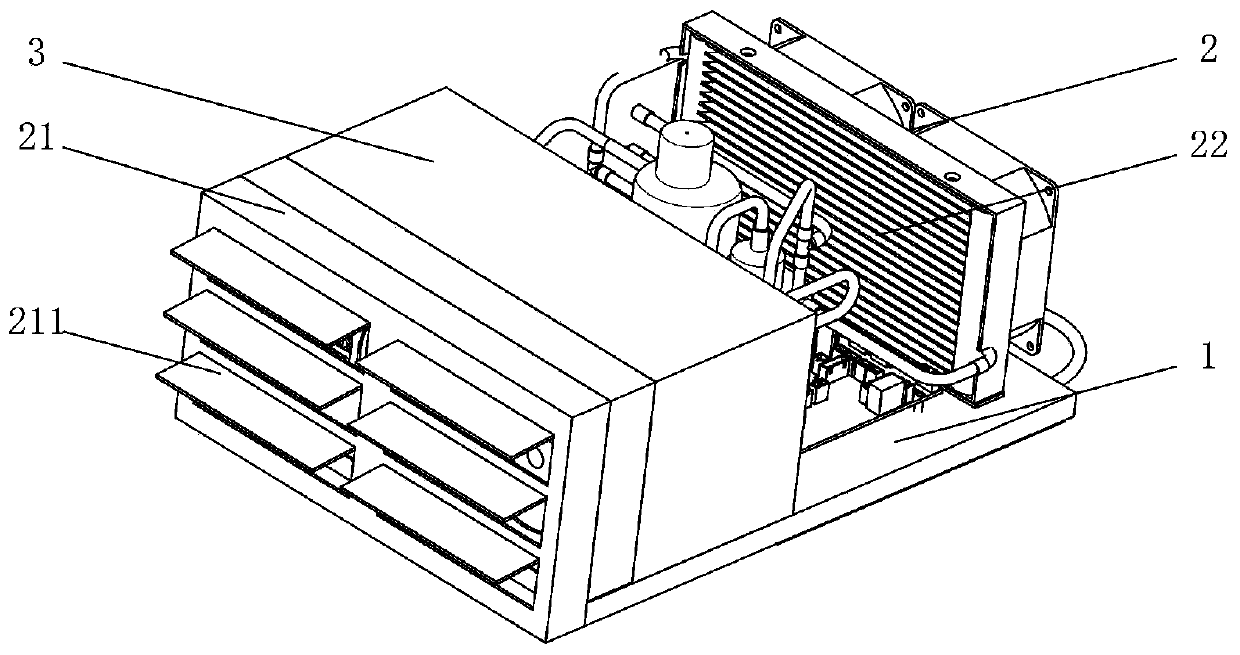
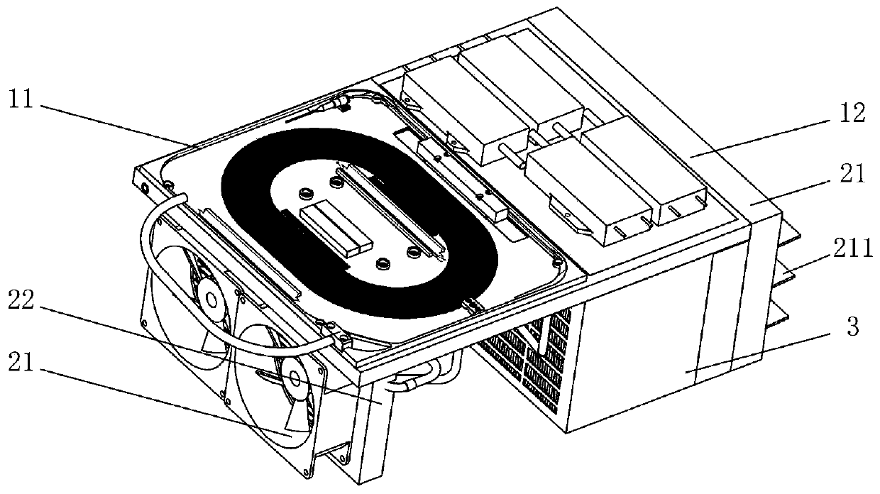
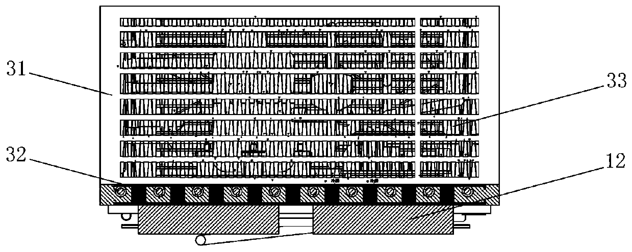
[0029] Such as figure 1 and figure 2 As shown, the composite heat dissipation non-water-cooled laser of this embodiment includes an optical system 1 and a heat dissipation device 2, and also includes a phase change heat dissipation system 3, and the heat dissipation device 2 can provide a cold source for the phase change heat dissipation system 3; the phase change heat dissipation system 3 includes The housing 31 is provided with a liquid pool 32 inside the housing 31 , and the bottom of the liquid pool 32 is close to the optical system 1 ; the housing 31 is also provided with a phase change material. When working, the optical system 1 will dissipate a large amount of heat, and the originally liquid phase-change material contained in the liquid pool 32 absorbs the heat dissipated by the optical system 1 and evaporates; since the cooling device 2 provides low temperature, the evaporated phase The variable material is liquefied after condensation, and returns to the liquid poo...


PUM

PropertyMeasurementUnit
Phase transition temperatureaaaaaaaaaa

Abstract

The invention discloses a composite heat dissipation water-cooling-free laser, which comprises an optical system, a heat dissipation device and a phase change heat dissipation system, and is characterized in that the heat dissipation device can provide a cold source for the phase change heat dissipation system; the phase change heat dissipation system comprises a shell; a liquid pool is arranged in the shell, and the bottom of the liquid pool is tightly attached to the optical system; a phase change material is further arranged in the shell, the liquid phase change material is contained in theliquid pool and absorbs heat emitted by the optical system to be evaporated, and the evaporated phase change material absorbs the low temperature provided by the heat dissipation device and is liquefied to return to the liquid pool. The composite heat dissipation water-cooling-free laser has the advantages of being simple in structure, light, easy to carry, good in heat dissipation effect, high in stability and the like.

Description

technical field [0001] The invention relates to the field of lasers, in particular to a composite heat-dissipating non-water-cooled laser. Background technique [0002] Existing water-free fiber lasers are widely used in industrial cutting, welding, mobile obstacle removal and other fields. With the development of water-free fiber lasers, the requirements for portability and light weight are getting higher and higher. Therefore, strict Limit its size, weight, energy consumption and other parameters. [0003] In the existing water-free fiber lasers, the laser diode often has a phenomenon that the wavelength drifts with the change of temperature due to problems such as insufficient heat dissipation and waste heat enrichment, so that the central wavelength does not match the main absorption peak of the gain medium, resulting in a decrease in absorption efficiency. The output power of the laser is reduced and it is difficult to meet the requirements of use. Therefore, the heat ...

Claims


Application Information

Patent Timeline
IPC IPC(8): H01S3/042H01S3/067
CPCH01S3/042H01S3/067
Inventor 郭少峰江厚满陈隧许波郑文雷
Owner 长沙大科光剑科技有限公司
Why Eureka
Try Eureka