
Electrified railway energy storage type traction power supply system and control method thereof

A technology for traction power supply systems and electrified railways, applied in electric braking systems, traction of AC induction motors, electrical components, etc., can solve problems such as loss of energy-consuming components, influence of power grids, and waste of electric energy, so as to reduce capacity and improve utilization efficiency, general applicability

Active Publication Date: 2020-02-21
SOUTHWEST JIAOTONG UNIV
View PDF8 Cites 25 Cited by
  • Summary
  • Abstract
  • Description
  • Claims
  • Application Information

AI Technical Summary

Problems solved by technology

On the one hand, when the train climbs, the load peak power becomes larger, thereby increasing the rated capacity of the traction transformer, but because the load rate of the traction transformer is not high, the utilization rate of the traction transformer is low and the economy is poor; on the other hand, The braking process of the train going downhill will generate more regenerative braking energy, which will either be sent back to the grid or lost by energy-consuming components, which will not only affect the grid, but also cause waste of electric energy

Method used


Image

  • Electrified railway energy storage type traction power supply system and control method thereof
  • Electrified railway energy storage type traction power supply system and control method thereof
  • Electrified railway energy storage type traction power supply system and control method thereof

Examples


Embodiment Construction

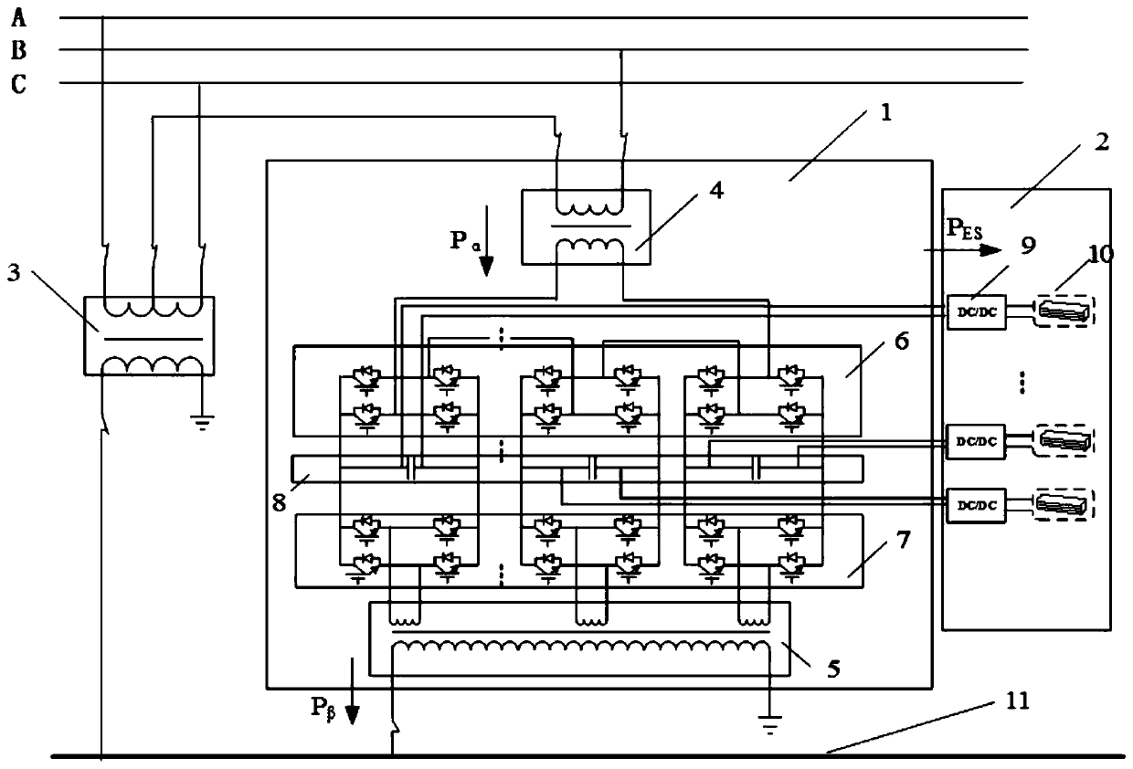
[0043] The present invention will be described in further detail below in conjunction with the accompanying drawings and specific embodiments. figure 1 Shown is a schematic diagram of the main circuit structure of an energy storage traction power supply system. The system is mainly composed of a power flow controller 1, an energy storage system 2 and a single-phase main traction transformer 3. It has the following functions: 1) The power flow controller works with the single-phase main traction transformer to balance the negative sequence current on the grid side; 2) The energy storage system works with the power flow controller to realize the feedback of train regenerative braking energy Utilization and traction load shaving.

[0044] The power flow controller 1 includes a high-voltage matching transformer 4, a grid-side AC-DC converter 6, a traction-side AC-DC converter 7, an intermediate DC-side capacitor 8, and a traction matching transformer 5; the primary side of the hi...


PUM


Abstract

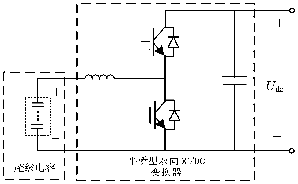
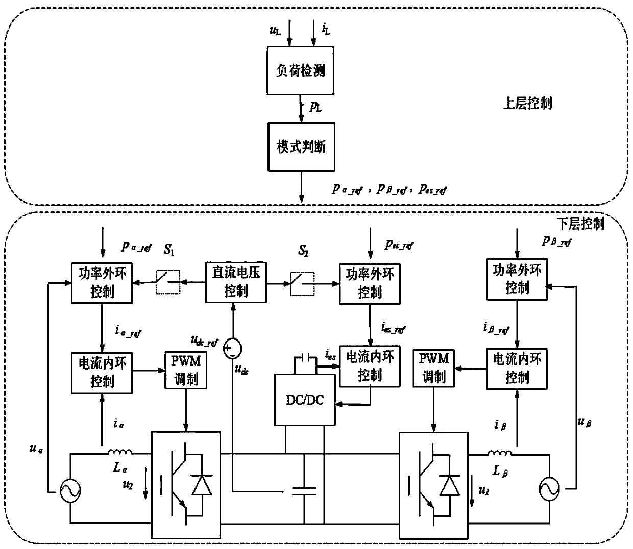
The invention discloses an electrified railway energy storage type traction power supply system and a control method thereof. The system comprises a power flow controller, an energy storage system anda single-phase main traction transformer. The power flow controller comprises a high-voltage matching transformer, a grid side AC / DC converter, a traction side AC / DC converter, an intermediate DC side capacitor and a traction matching transformer. The energy storage system comprises a bidirectional DC / DC converter and an energy storage element, and the energy storage element is connected in parallel to the intermediate DC side capacitor through the bidirectional DC / DC converter. The control method comprises the following steps: collecting voltage and current data of a load at the outlet of asubstation, judging the operation condition of the system, and calculating the compensation power of the ports of the power flow controller and the energy storage device under each condition; adding the compensation power into double-loop control of a power outer loop and a current inner loop to obtain a modulation signal; and generating a switching signal of a control device through PWM modulation. Recovery and reutilization of the regenerative braking energy of trains are achieved, the utilization rate of the regenerative braking energy is increased, and negative-sequence electric energy quality treatment and compensation device capacity optimization are achieved.

Description

technical field [0001] The invention relates to the technical field of traction power supply for electrified railways, in particular to an energy storage type traction power supply system for electrified railways and a control method thereof. Background technique [0002] The single-phase power frequency AC power supply system of electrified railways and the characteristics of large power and asymmetry of traction loads have caused the power quality problems of the system mainly negative sequence, affecting the safe, reliable and efficient operation of electrified railways. At the same time, with the extension of electrified railway lines to high-altitude areas in western my country, there are often situations with large line slopes, many tunnels, and frequent regenerative braking of trains. For example, the maximum slope of the Baolan Passenger Dedicated Line and Xicheng Passenger Dedicated Line reaches 25‰, and the proportion of bridges and tunnels in the cross-mountain se...

Claims


Application Information

Patent Timeline
Patent Type & Authority Applications(China)
IPC IPC(8): H02J3/06H02J3/32H02J3/00B60L9/24B60L7/14
CPCH02J3/06H02J3/32H02J3/00B60L9/24B60L7/14
Inventor 陈民武程一林程哲吕亚博张迪雅陈垠宇陈迎涛刘若飞
Owner SOUTHWEST JIAOTONG UNIV
Learn More