Luminescent ceramics and wavelength converter
A technology of wavelength conversion device and luminescent ceramics, applied in luminescent materials, chemical instruments and methods, electrical components, etc., can solve problems such as the reduction of luminous amount, and achieve the effect of being less prone to light degradation
- Summary
- Abstract
- Description
- Claims
- Application Information
AI Technical Summary
Problems solved by technology
Method used
Image

Examples
experiment example
[0048] Next, the present invention will be further described in detail by describing experimental examples of the luminescent ceramics of the present invention. In addition, this invention is not limited to the following experimental example.
[0049] Hereinafter, the present invention will be described more specifically by giving specific experimental examples of the present invention.
experiment example 1
[0051] As a raw material, prepare La(OH) 3 、Gd 2 o 3 , Y 2 o 3 , Yb 2 o 3 、Lu 2 o 3 , ZrO 2 , HfO 2 , SnO 2 , Nb 2 o 5 、 Ta 2 o 5 , Sb 2 o 3 and Bi 2 o 3 . These raw materials were weighed so that the compositions shown in the molar ratios in Table 1 below were obtained, and wet mixing was performed for 20 hours using a ball mill. After drying the obtained mixture, it baked at 1300 degreeC for 3 hours, and obtained the baked product. The obtained calcined product was put into a ball mill together with water and an organic dispersant, and wet pulverized for 12 hours. Using the obtained pulverized product, it was molded into a disk-like shape with a diameter of 30 mm and a thickness of 5 mm by a wet molding method. The obtained molded product was embedded in a powder having the same composition as the molded product, and fired at a temperature of 1700°C for 20 hours in an oxygen atmosphere (about 98 vol% oxygen concentration). Thus a sintered body was obtai...
experiment example 2
[0069] In the same manner as in Experimental Example 1, samples for evaluation of Sample No. 15 to Sample No. 42 shown in Table 2, Table 3, and Table 4 below were obtained.
[0070] For each of the obtained samples for evaluation, the quantum yield, in-line transmittance, and relative luminous intensity were determined in the same manner as in Experimental Example 1. The results are shown in Table 2, Table 3 and Table 4 below. It should be noted that the feed composition ratios in Table 2, Table 3, and Table 4 are molar ratios, and are values normalized so that X+Y+Z=2.0. In addition, the values of X, Y, and Z were set so as to satisfy 3X+4Y+5Z=7.0 or its vicinity similarly to Experimental Example 1. The values of X, Y, and Z are also shown together in Table 2, Table 3, and Table 4 below.
[0071]
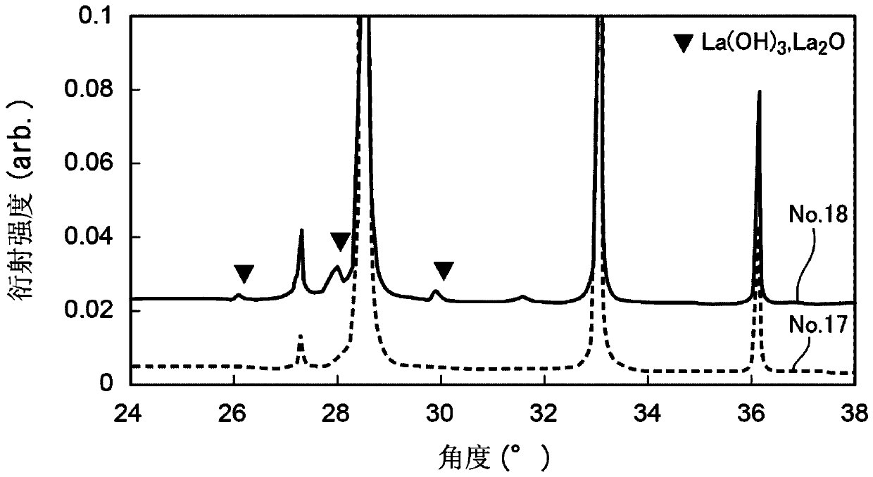
[0072] Sample No. 15 to Sample No. 18 in Table 2 show the results when Ta is the pentavalent ion Z=0.050 and the total charge of the cation, that is, 3X+4Y+5Z deviates f...
PUM
| Property | Measurement | Unit |
|---|---|---|
| thickness | aaaaa | aaaaa |
| transmittivity | aaaaa | aaaaa |
Abstract
Description
Claims
Application Information
 - R&D
- Intellectual Property
- Life Sciences
- Materials
- Tech Scout
- Unparalleled Data Quality
- Higher Quality Content
- 60% Fewer Hallucinations
Browse by: Latest US Patents, China's latest patents, Technical Efficacy Thesaurus, Application Domain, Technology Topic, Popular Technical Reports.
© 2025 PatSnap. All rights reserved.Legal|Privacy policy|Modern Slavery Act Transparency Statement|Sitemap|About US| Contact US: help@patsnap.com