Boiler blowdown recycling method and device

A boiler blowdown and boiler technology, applied in boiler cleaning devices, separation methods, chemical instruments and methods, etc., can solve problems such as waste

Inactive Publication Date: 2020-02-25
YANKUANG GUOHONG CHEM
View PDF6 Cites 0 Cited by
  • Summary
  • Abstract
  • Description
  • Claims
  • Application Information

AI Technical Summary

Problems solved by technology

[0005] Aiming at the problems of the prior art that continuous drainage is discharged without utilization, which causes a large amount of heat waste and great thermal pollution, the present invention provides a method and device for recycling boiler sewage. The method conforms to the national energy-saving policy and significantly saves energy The effect can completely change the working environment, reduce environmental heat pollution and improve the atmospheric environment. At the s...

Method used


Image

  • Boiler blowdown recycling method and device
  • Boiler blowdown recycling method and device

Examples


Embodiment 1

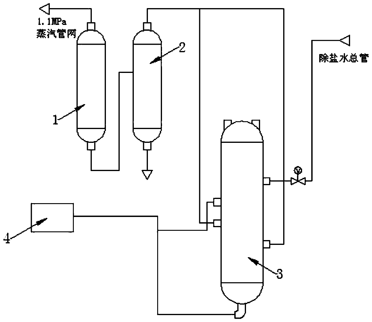
[0040] Such as figure 1 Shown, a kind of boiler sewage recycling method, described method comprises the following steps:

[0041] S1: The continuous drainage of the boiler enters the continuous expansion vessel 1 for flash evaporation to obtain saturated steam and high-temperature water;

[0042] S2: The high-temperature water obtained in S1 is discharged into the fixed discharge tank 2, and flashed together with the system drainage discharged into the fixed discharge tank 2 to obtain exhausted steam and water;

[0043] S3: The exhaust steam enters the absorption tower 3 to be liquefied to obtain high-temperature water;

[0044] S4: The high-temperature water obtained in S3 enters the gas-water separation device, and the non-condensable gas in the water is separated and discharged;

[0045] S5: The high-temperature water after the non-condensable gas is separated in S4 enters the deaerator 4 .

Embodiment 2

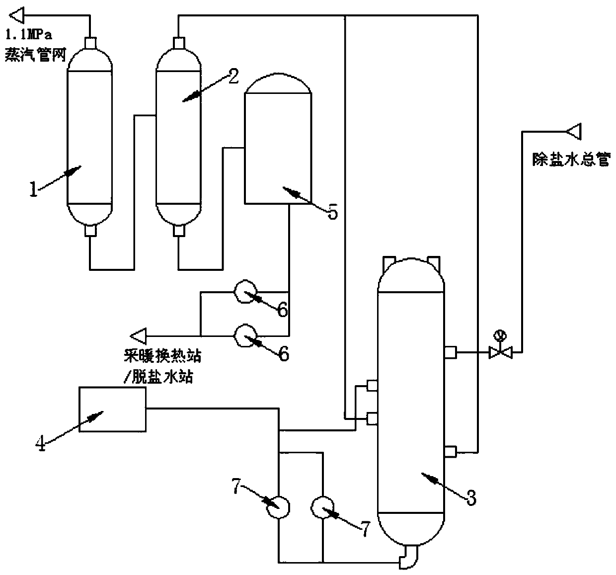
[0047] Such as figure 2 Shown, a kind of boiler sewage recycling method, described method comprises the following steps:

[0048] S1: The continuous drainage of the boiler enters the continuous expansion vessel 1 for flash evaporation to obtain saturated steam and high-temperature water, and the saturated steam is merged into the 1.1MPa pipe network for heating in chemical production;

[0049] S2: The high-temperature water obtained in S1 is discharged into the fixed row tank 2, and flashed together with the system drainage discharged into the fixed row tank 2 to obtain exhaust steam and water, and the water is discharged into the drain tank 5, and the water in the drain tank 5 It is discharged through the drain pump 6, used as hot water in the heating water system of the heat exchange station during the heating period, and part of the hot water is used as replenishment for the raw water system of the desalinated water station when it is in excess; it is used as replenishment f...

Embodiment 3

[0055] Such as figure 1 As shown, a boiler blowdown recovery and utilization device, said device includes a continuous expansion vessel 1, a fixed discharge tank 2, an absorption tower 3 and a deaerator 4, and the continuous expansion vessel 1 is provided with a continuous drainage inlet and a steam outlet and a high-temperature water outlet, the fixed discharge tank 2 is provided with a high-temperature water inlet, a exhaust steam outlet and a drain outlet, and the absorption tower 3 is provided with a exhaust steam inlet, a high-temperature water outlet and a non-condensable gas outlet, and the absorption tower 3 interior An ejector and a gas-water separation device are provided, and the deaerator 4 includes a high-temperature water inlet, a high-temperature water outlet and an oxygen outlet;

[0056] The high-temperature water outlet of the continuous expansion vessel 1 is connected with the high-temperature water inlet of the fixed row tank 2, the exhaust steam outlet of ...


PUM


Abstract

The invention relates to the technical field of boiler blowdown recycling, in particular to a boiler blowdown recycling method and device. The method comprises the following steps that boiler continuous blowdown water enters a continuous blowdown flash tank to obtain saturated steam and high-temperature water, the high-temperature water and system drainage water discharged into a periodic blowdowntank are subjected to flash evaporation to obtain exhaust steam, the exhaust steam enters an absorption tower to be liquefied to obtain high-temperature water, and the high-temperature water enters agas-water separation device to separate non-condensable to be discharged, and then enters a deaerator. The device comprises the continuous blowdown flash tank, the periodic blowdown tank, the absorption tower and the deaerator, wherein a high-temperature water outlet of the continuous blowdown flash tank is connected with a high-temperature water inlet of the periodic blowdown tank, an exhaust steam outlet of the periodic blowdown tank is connected with an exhaust steam inlet of the absorption tower, and a high-temperature water outlet of the absorption tower is connected with a high-temperature water inlet of the deaerator. According to the boiler blowdown recycling method and device, the national energy-saving policy requirement is met, the energy saving effect is obvious, the working environment is completely changed, the environmental thermal pollution is reduced, the atmospheric environment is improved, the carbon emission is reduced, resources are saved, the resource utilizationtime is prolonged, and good economic benefits are achieved.

Description

technical field [0001] The invention relates to the technical field of recycling boiler blowdown, in particular to a method and device for recycling boiler blowdown. Background technique [0002] A thermal power plant refers to a thermal power plant that can use steam extraction or exhaust steam from a steam turbine to provide heat to users while generating electricity. High-pressure boiler is one of the indispensable equipment of thermal power plant. It discharges a large amount of sewage during operation, and the sewage discharge can reach 10 tons per hour. [0003] One existing technology is to lead the continuous drainage of the boiler to the continuous expansion vessel for flash evaporation, and the 0.35MPa steam obtained by the flash evaporation is sent to the steam inlet pipeline of the deaerator, and the continuous high-temperature water is sent to the regular sewage discharge pipe, and then Discharged to the ditch by a fixed row. Due to the long distance between t...

Claims


Application Information

Patent Timeline
IPC IPC(8): F22D1/50F22B37/54
CPCF22B37/54F22D1/50
Inventor 田希源王伟王耸张奎同郑恒闵祥坤范伟尹振春朱广东马国石磊
Owner YANKUANG GUOHONG CHEM
Why Eureka
Try Eureka