
Welding method of heavy-duty universal joint shaft intermediate shaft

A universal joint shaft and intermediate shaft technology, applied in welding equipment, welding accessories, arc welding equipment, etc., can solve the problems of large difference in size between the upper and lower sides of the groove angle weld, early failure of the product, and large shrinkage, etc., to achieve production The effect of cost reduction, guaranteed performance and improved performance

Active Publication Date: 2022-07-08
TAIER HEAVY IND
View PDF11 Cites 0 Cited by
  • Summary
  • Abstract
  • Description
  • Claims
  • Application Information

AI Technical Summary

Problems solved by technology

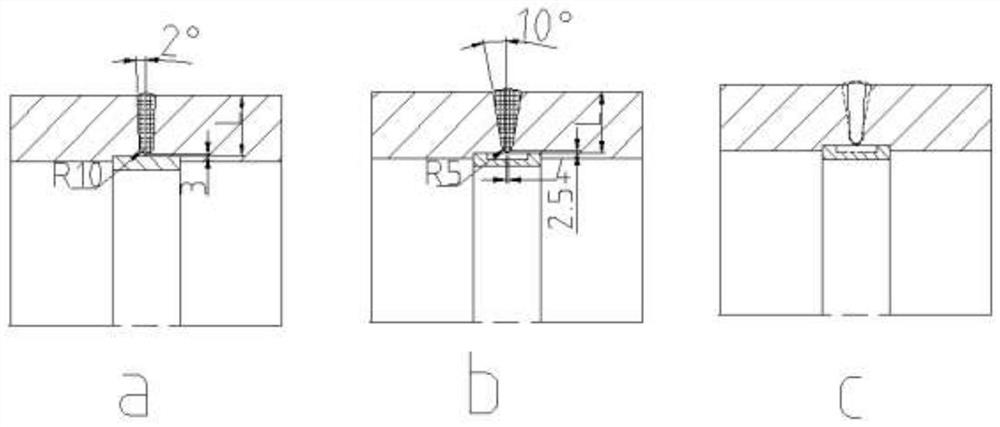
[0006] However, if the performance and quality of the weld between the two parts cannot be guaranteed, it is easy to break at the weld during use. There are two situations: one is that if the bottom of the weld is not penetrated, When the large shaft is subjected to torque and bending moment, it becomes the source of cracks, resulting in fractures extending from the inside to the outside; another type, if the groove angle of the weld structure design is too large, the difference in the upper and lower dimensions of the weld will be large, and the upper part will shrink during welding. Pulling the base metal on both sides of the weld will cause the fusion line in the upper half of the weld to break from the outside to the inside, resulting in early failure of the product

Method used


Image

  • Welding method of heavy-duty universal joint shaft intermediate shaft
  • Welding method of heavy-duty universal joint shaft intermediate shaft
  • Welding method of heavy-duty universal joint shaft intermediate shaft

Examples


Embodiment 1

[0053] The rotation diameter of the 3500 wide and thick plate roughing line in a steel plant is as follows: The welding method of the present invention will be described in detail by taking a universal joint shaft of a rolling mill as an example.

[0054] The maximum power of the motor end of the connecting shaft is 8000KW, the motor speed is 45-90 rpm, and the design weight of the connecting shaft is 41.6 tons. According to the maximum transmission torque, fatigue torque, motor power and rotational speed, the transmission torque of the connecting shaft can be calculated to be 1698 (kN m), and the motor overload coefficient is 2.75. The maximum overload torque of the universal joint shaft used in this rolling line is 10200 ( kN m), the fatigue torque is 4830 (kN m).

[0055] The overall length of the whole heavy-duty universal joint shaft is 13.55 meters and the weight is 46.83 tons. The outer diameter of the welding part of the intermediate shaft is The length is 9.68 met...


PUM

PropertyMeasurementUnit
thicknessaaaaaaaaaa
lengthaaaaaaaaaa
lengthaaaaaaaaaa

Abstract

The invention discloses and provides a welding method for a heavy-duty universal joint shaft intermediate shaft used in a rough rolling steel production line. The heavy-duty universal joint shaft intermediate shaft of the present invention comprises a bracket shaft 1, a connecting pipe I2, a connecting pipe II3, a welding flange I, and a welding flange II5. Sequentially, it is welded with the nozzle and the welding flange in two symmetrical segments, that is, firstly, the left and right sides of the bracket shaft 1 are welded with the nozzle I2 and the nozzle II3 in sequence, then the nozzle I2 is welded with the welding flange I4, and the nozzle II3 is welded with the welding Flange II5 is welded to form the whole of the intermediate shaft. The advantages of the intermediate shaft group welding method of the present invention are as follows: firstly, its welding seam performance is good, and it is not easy to break, which ensures the use performance of the connecting shaft in the rolling process; secondly, the welding efficiency is high, and the production cost is greatly reduced.

Description

technical field [0001] The invention relates to a welding method for a heavy-duty universal joint shaft intermediate shaft of a rough rolling line of metallurgical equipment, more particularly, the invention relates to a welding method with a length of more than 5 meters, a rotation diameter of 600mm-1400mm, and a welding seam wall thickness of 60mm-100mm The welding method of the heavy-duty universal joint shaft intermediate shaft. Background technique [0002] The heavy-duty universal joint shaft in the present invention is used in the rough rolling steel production line in metallurgical equipment, and its working conditions are: working temperature: -20~+80°C; transmission torque range: 1085KN.m~9190KN.m; overload limit Torque is 2300kN.m~19405kN.m; Rotation diameter: 600mm~1400mm; the connecting shaft requires high bearing capacity, long service life and transmission efficiency as high as 98.7%-99.9% in the process of steel plate rolling. [0003] The intermediate shaft...

Claims


Application Information

Patent Timeline
Patent Type & Authority Patents(China)
IPC IPC(8): B23K9/18B23K9/32B23K9/02
CPCB23K9/18B23K9/32B23K9/02Y02P70/10
Inventor 杨晓红黄东保方凯朱健平许训国竹节武支强
Owner TAIER HEAVY IND
Learn More