A testing device for flatness and tensile strength of sewing parts

A technology for strength detection and flatness, which is applied in the direction of measuring devices, mechanical roughness/irregularity measurement, strength characteristics, etc., can solve the problems of fabric anti-pull detection flatness, detection, etc., to achieve a large clamping range and improve Robustness and the effect of improving detection efficiency

Active Publication Date: 2021-12-17
济宁天久工贸有限公司
View PDF12 Cites 0 Cited by
  • Summary
  • Abstract
  • Description
  • Claims
  • Application Information

AI Technical Summary

Problems solved by technology

[0005] A device for detecting the degree of pull resistance of non-woven fabrics in the above-mentioned patent has the following disadvantages: when the device is in use, it can only detect pieces of cloth, and cannot perform pull resistance detection and flatness detection on the processed and sewn cloth.

Method used


Image

  • A testing device for flatness and tensile strength of sewing parts
  • A testing device for flatness and tensile strength of sewing parts
  • A testing device for flatness and tensile strength of sewing parts

Examples


Embodiment 1

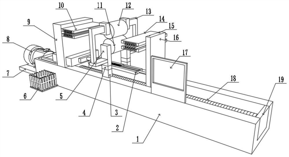
[0034] A device for testing the flatness and tensile strength of sewing parts, such as figure 1 As shown, it includes a fixed base 1, the side wall of the fixed base 1 is welded with a motor platform 7, the top of the motor platform 7 is fixed with a motor 8, and the output shaft of the motor 8 is connected with a lead screw 18 through a coupling. One end of the bar 18 is fixed with a stopper 19 through a bearing, the stopper 19 is welded to the inner wall of the fixed seat 1, the outer wall slider of the lead screw 18 is connected with a moving frame 16, and one side of the top of the fixed seat 1 is welded with a fixed frame 9 , the top of the outer wall on one side of the fixed frame 9 is provided with a fixed clamping frame 10, the top of the outer wall on one side of the moving frame 16 is provided with a mobile clamping frame 14, and a tension gauge 2 is arranged between the fixed frame 9 and the moving frame 16;

[0035] Both sides of the top of the fixed seat 1 are wel...

Embodiment 2

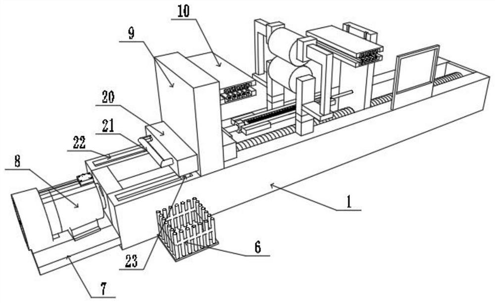
[0045] A device for testing the flatness and tensile strength of sewing parts, such as Figure 5 with Image 6 As shown, in order to solve the problem that it is inconvenient to detect the tensile strength at the corners of the cloth; this embodiment makes the following improvements on the basis of embodiment 1: one of the pillars 3 is fixed to the top of the fixed seat 1 by a hinge shaft 33, One end of another pillar 3 is fixed to the top of the fixed seat 1 by a fixed pin, and the pillar 3 can be rotated by the hinge shaft 33, so that the lower pressing roller 11 and the upper pressing roller 12 can be turned over to the fixed seat 1 side, thereby avoiding pressing down. The influence of roller 11 and upper pressure roller 12 on the detection of tensile capacity;


PUM


Abstract

The invention discloses a device for detecting the flatness and tensile strength of sewing parts, which relates to the technical field of textile cloth production; in order to solve the problem that only the cloth can be detected but the cloth after sewing cannot be tested for pulling resistance and flatness; it specifically includes A fixed seat, the side wall of the fixed seat is welded with a motor table, the top of the motor table is fixed with a motor through a bolt, the output shaft of the motor is connected with a lead screw through a coupling, and one end of the lead screw is fixed with a stopper through a bearing. The block is welded to the inner wall of the fixed seat, the outer wall slider of the lead screw is connected with a movable frame, one side of the top of the fixed seat is welded with a fixed frame, the top of the outer wall of one side of the fixed frame is provided with a fixed clamping frame, and one side of the movable frame is The top of the outer wall is provided with a movable clamping frame. The present invention provides a fixed clamping frame and a movable clamping frame with a rectangular sheet structure, so that the clamping range is large, so that the clamping position can be adjusted according to requirements, and the flexibility of equipment use is improved.

Description

technical field [0001] The invention relates to the technical field of textile cloth production, in particular to a device for detecting the flatness and tensile strength of sewing parts. Background technique [0002] The original meaning of textile is taken from the general term of spinning and weaving, but with the continuous development and improvement of the textile knowledge system and subject system, especially after the emergence of non-woven textile materials and three-dimensional composite weaving technologies, the current textile is not only a traditional Hand spinning and weaving also include clothing, industrial and decorative textiles produced by non-woven technology, modern three-dimensional weaving technology, and modern electrostatic nano-netting technology; therefore, modern textile refers to a kind of fiber or fiber collection Solid multi-scale structure processing technology. [0003] Clothing production often uses sewing machines to sew, and after sewing...

Claims


Application Information

Patent Timeline
Patent Type & Authority Patents(China)
IPC IPC(8): G01B5/28G01N3/04G01N3/08
CPCG01B5/28G01N3/04G01N3/08G01N2203/0017G01N2203/0282G01N2203/0423
Inventor 刘桂保谭件文刘功林
Owner 济宁天久工贸有限公司
Why Eureka
Try Eureka