Kitchen appliance containing cover closing safety protection linkage assembly and control method of kitchen appliance

A technology for kitchen utensils and linkage components, which is applied in the directions of kitchen utensils, program control, computer control, etc., can solve the problems of difficult cleaning, difficult installation, and inability to detect the installation of the mixing cup, so as to reduce the probability of mechanical danger and reduce mechanical Hazard probability, the effect of reducing the chance of mechanical hazards

Pending Publication Date: 2020-03-06
SHANGHAI CHUNMI ELECTRONICS TECH CO LTD
View PDF0 Cites 4 Cited by
  • Summary
  • Abstract
  • Description
  • Claims
  • Application Information

AI Technical Summary

Problems solved by technology

At present, the safety protection device for the lid of the cooking machine on the market is inserted into a small gap through the edge of the cup lid, and the micro switch is touched for protection. After passing the

Method used


Image

  • Kitchen appliance containing cover closing safety protection linkage assembly and control method of kitchen appliance
  • Kitchen appliance containing cover closing safety protection linkage assembly and control method of kitchen appliance
  • Kitchen appliance containing cover closing safety protection linkage assembly and control method of kitchen appliance

Examples


Embodiment 1

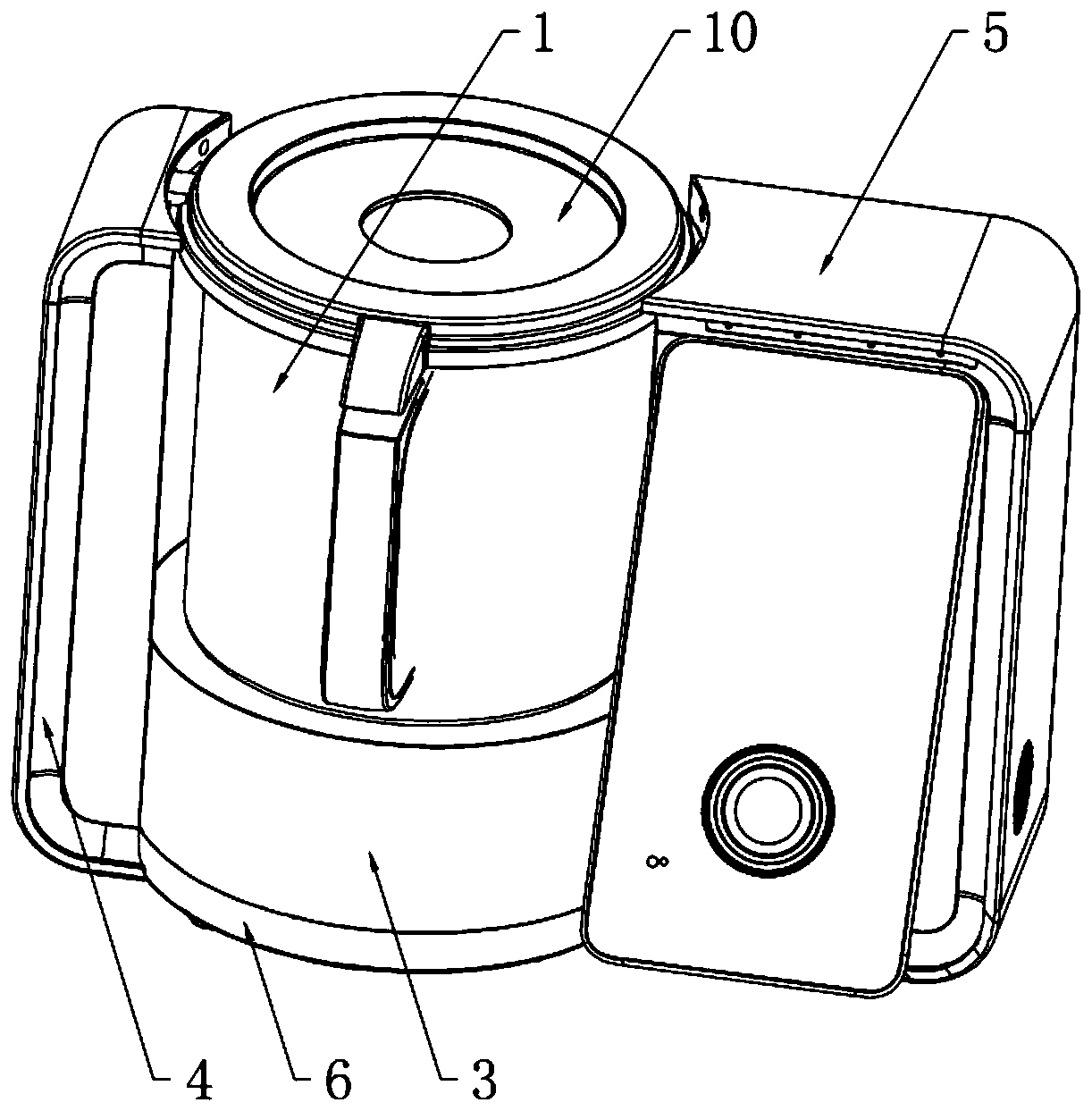
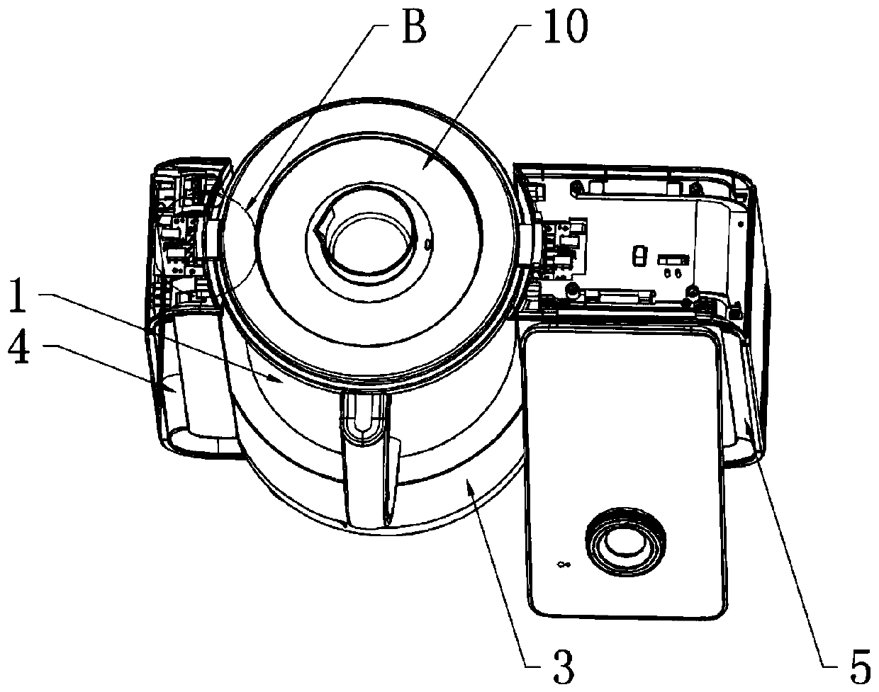
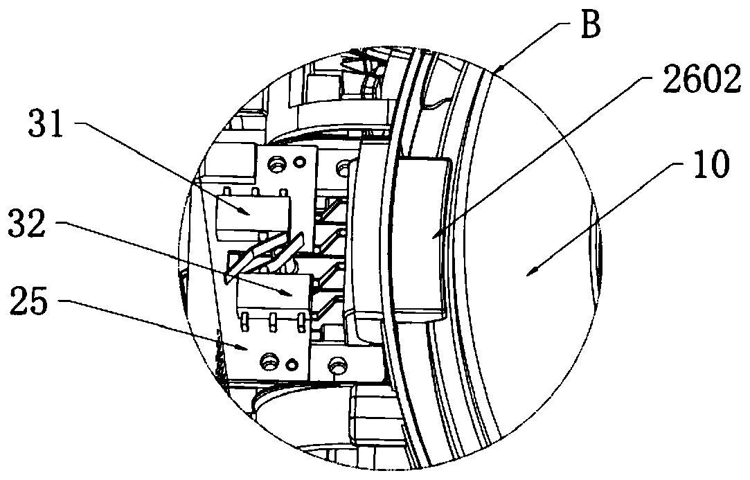
[0089] A kitchen appliance including a lid closing safety protection linkage assembly, comprising an installation shell 1, a main body shell 3 equipped with a switched reluctance motor 2 inside, a handle shell 4 fixedly connected to both sides of the main body shell 3, and a control shell 5. And the base 6 assembled on the lower end of the host housing 3, the handle housing 4, and the control housing 5. The control housing 5 is equipped with a PCB board 7 and a micro control unit MCU for controlling the work of the kitchen appliance; the host housing The upper end of 3 is formed with a housing bracket 8 for assembling the installation housing 1, and the installation housing 1 is equipped with a container assembly, and the container assembly includes a heating container 9, a container cover 10 fastened on the heating container 9, A container in-position detection structure is provided between the container assembly, the installation shell 1, and the shell bracket 8. The handle s...

Embodiment 2

[0101] Embodiment 2 of the present invention is further improved on the basis of Embodiment 1, so as to fully exert the technical advantages of the present invention, which will be illustrated below.

[0102] For example, the heating container 9 is also provided with a stirring assembly for food stirring, and the stirring assembly includes an arc cutter 23 matched with the bottom of the heating container, and the lower end of the arc cutter 23 is connected to the switched reluctance motor 2 drive connections. The arc cutter 23 drives the food to stir / stir in the process of rotation, which not only helps to improve the stirring performance of the food, but also prevents the bottom of the heating container 9 from sticking. The lower end of the cutter shaft of the arc cutter 23 passes through the connecting portion It is connected with the motor shaft of the switched reluctance motor 2, and the detachable function of the stirring assembly can be realized through the connection of...

Embodiment 3

[0106] Embodiment 3 of the present invention is further improved on the basis of Embodiment 1 so as to fully exert the technical advantages of the present invention, which will be illustrated below.

[0107] For example: the exterior of the control shell is equipped with an angle-adjustable display screen assembly 61, which can adjust the inclination angle of the display screen assembly 61 according to the user's height and usage habits. The display screen assembly 61 includes a display screen shell, a display screen, a knob, And the display screen electronic board located in the display screen housing, the display screen and the knob are electrically connected to the display screen electronic board respectively, the display screen electronic board is electrically connected to the micro control unit MCU, and the required setting is adjusted by rotating the knob The time, temperature, speed, weight, etc. of the device are displayed on the display screen. Between the handle shell...


PUM


Abstract

The invention relates to a kitchen appliance containing a cover closing safety protection linkage assembly and a control method of the kitchen appliance. The kitchen appliance comprises a mounting shell body, a main engine shell body internally provided with a switched reluctance motor, a handle shell, a control shell and a base, wherein the handle shell, the control shell and the base are fixedlyconnected to the two sides of the main engine shell body respectively; a shell bracket for assembling the mounting shell body is assembled at the upper end of the main engine shell body, a containerassembly is arranged on the mounting shell body, the container assembly comprises a heating container and a container cover buckled on the heating container, a container in-place detection structure is arranged among the container assembly, the mounting shell body and the shell bracket, the handle shell and the control shell are respectively provided with at least one cover closing safety protection linkage assembly; and the cover closing safety protection linkage assembly comprises at least one container cover locking structure and at least one cover closing in-place detection structure. According to the kitchen appliance and the control method in the invention, by using the container in-place detection structure, the cover closing in-place detection structure and the container cover locking structure in combination, cover closing safety is protected, the safety requirement is met, and the probability of occurrence of mechanical danger is greatly reduced.

Description

technical field [0001] The invention belongs to the technical field of kitchen appliances, and in particular relates to a kitchen appliance including a lid closing safety protection linkage assembly and a control method thereof. Background technique [0002] The cooking machine is a new generation of microcomputer-controlled intelligent cooking equipment. The equipment is mainly convenient, simple to operate, and has no oil fume. Frying, cooking, frying, popping, braising, steaming, boiling, roasting, stewing, stewing and other multi-purpose functions in one pot can easily realize the automation and fun of the cooking process. At present, the safety protection device for the lid of the cooking machine on the market is inserted into a small gap through the edge of the cup lid, and the micro switch is touched for protection. After passing the safety test, this kind of device is not easy to install. If there is an object in the gap, it is difficult to clean. A blockage will no...

Claims


Application Information

Patent Timeline
IPC IPC(8): A47J27/00A47J36/00A47J36/06A47J36/10G01G17/00G01G19/52G05B19/042
CPCA47J27/004A47J36/00A47J36/06A47J36/10G01G17/00G01G19/52G05B19/042
Inventor 杨华杨有如郑秀谦刘锦森陈华山肖靖鹏戴建亮刘福波陈良麟陈巍贾贵胜
Owner SHANGHAI CHUNMI ELECTRONICS TECH CO LTD
Why Eureka
Try Eureka