[0021] The technical solutions in the embodiments of the present invention will be clearly and completely described below in conjunction with the accompanying drawings in the embodiments of the present invention. Obviously, the described embodiments are only a part of the embodiments of the present invention, rather than all of them. Based on the embodiments of the present invention, all other embodiments obtained by those of ordinary skill in the art without creative work fall within the protection scope of the present invention.
[0022] It should be noted that all directional indicators (such as up, down...) in the embodiments of the present invention are only used to explain the relative positional relationship, movement, etc., between the components in a specific posture (as shown in the drawings). If the specific posture changes, the directional indication changes accordingly.
[0023] In addition, in the present invention, descriptions involving "first", "second", etc. are only for descriptive purposes, and cannot be understood as indicating or implying their relative importance or implicitly indicating the number of indicated technical features. Therefore, the features defined with "first" and "second" may explicitly or implicitly include at least one of the features.
[0024] Moreover, the technical solutions between the various embodiments of the present invention can be combined with each other, but they must be based on what can be achieved by a person of ordinary skill in the art. When the combination of technical solutions is contradictory or cannot be achieved, it should be considered that this combination of technical solutions It does not exist and does not fall within the scope of protection claimed by the present invention.
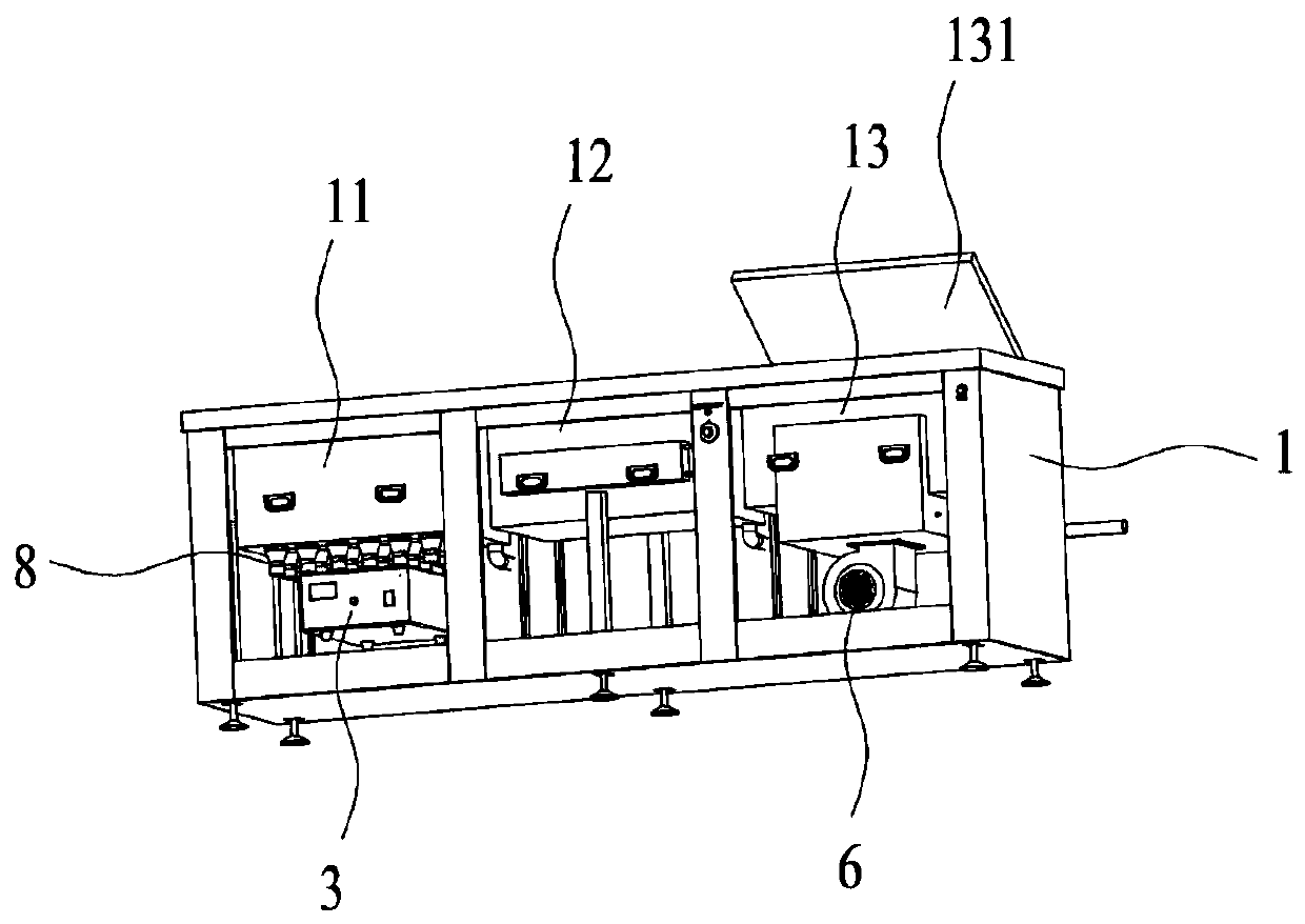
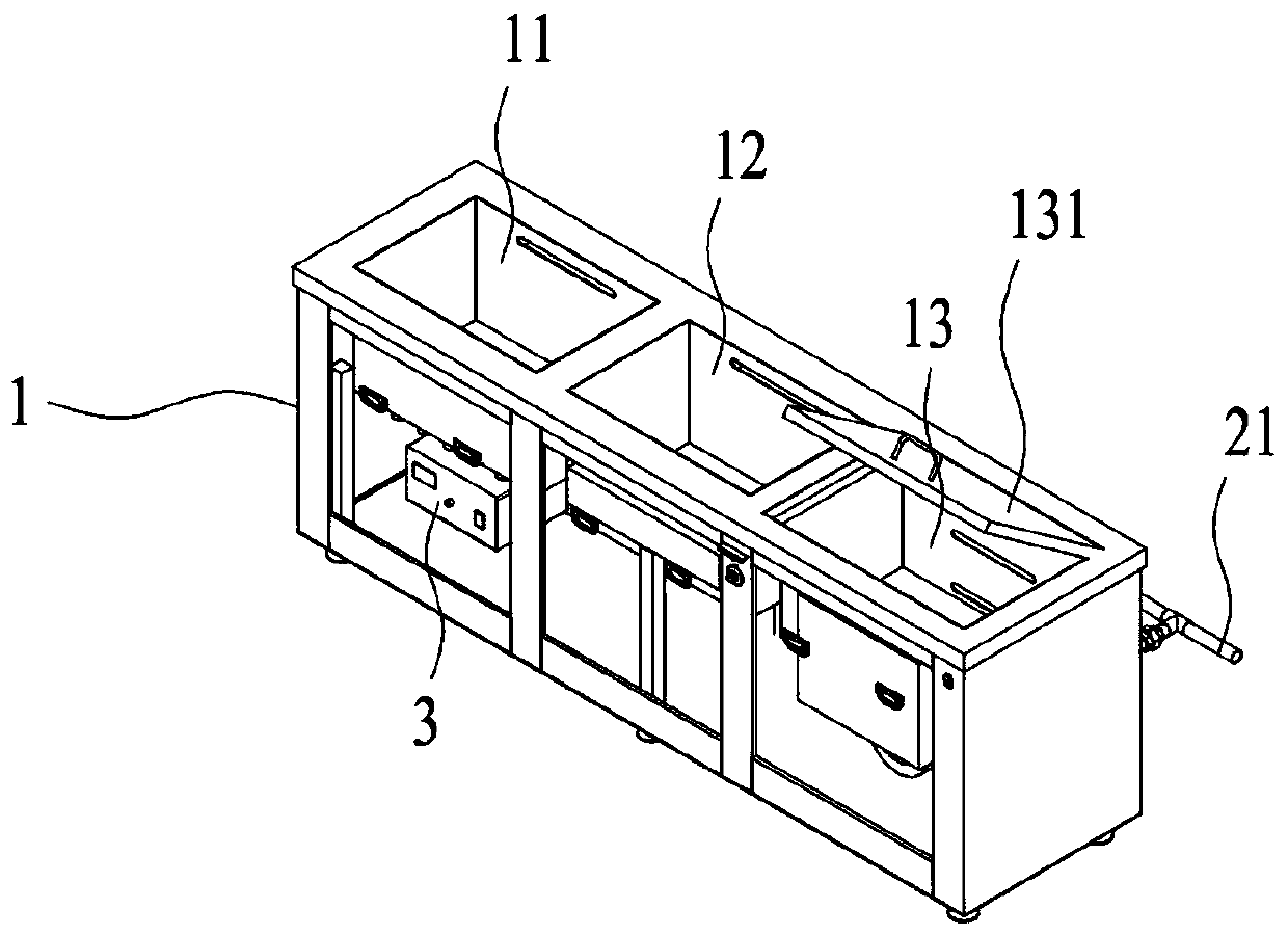
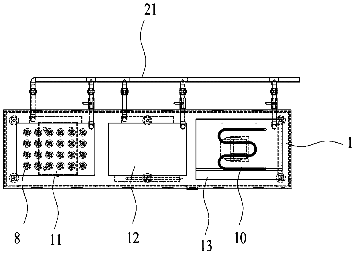
[0025] See figure 1 — Figure 4 , The present invention provides a cleaning device for calculus surgery. The cleaning device includes: a casing 1; the casing 1 is provided with a cleaning tank 11, a rinsing tank 12 and a drying tank 13, and the bottom of the cleaning tank 11 is equipped with an ultrasonic vibrator 3, A hot air blower 6 is installed at the bottom of the drying tank 13; a water pump and a water pipe connected to the water pump. The water pipe includes a main water pipe 21 and a first water inlet pipe 22, a first water outlet pipe 24, a second water inlet pipe 23, and a first water inlet pipe 22 connected to the main water pipe 21. Two water outlet pipes 25, the first water inlet pipe 22 and the first water outlet pipe 24 are respectively connected to the cleaning tank 11, and the second water inlet pipe 23 and the second water outlet pipe 25 are connected to the rinsing tank 12 respectively. In the above embodiment, the cleaning liquid is injected into the cleaning tank 11 and the rinsing tank 12 through the main water pipe 21, the first water inlet pipe 22, and the second water inlet pipe 23, respectively, and the ultrasonic vibrator 3 installed at the bottom of the cleaning tank 11 controls the cleaning tank. The parts to be cleaned in 11 are subjected to ultrasonic cleaning, and hot air is blown into the drying tank 13 through a hot air blower 6 installed at the bottom of the drying tank 13 to dry the parts to be cleaned. This embodiment uses ultrasonic vibration to clean the parts to be cleaned without damaging the parts to be cleaned, and realizes an integrated design of cleaning, rinsing and drying on the same cleaning device, which is very convenient for cleaning and drying. The above-mentioned object to be cleaned may be a laser fiber tube used in holmium laser lithotripsy (especially for treatment of kidney stones). Water pumps are used to provide power for water intake and drainage. According to a preferred embodiment of the present invention, a plurality of uniformly distributed plastic parts 8 are further provided at the bottom of the cleaning tank 11, and the ultrasonic vibrator 3 is connected to the cleaning tank 11 through the plastic parts 8. The multiple plastic parts 8 are provided to enable the ultrasonic vibration emitted by the ultrasonic vibration part to be uniformly transmitted to the entire cleaning tank 11.
[0026] The cleaning device in this embodiment also includes a first control valve and a second control valve. The first control valve is installed in the first water outlet pipe 24 and the second control valve is installed in the second water outlet pipe 25. When the cleaning liquid in the cleaning tank 11 or the rinsing tank 12 needs to be replaced, the first valve 71 can be opened to drain the cleaning liquid in the cleaning tank 11 through the first outlet pipe 24, and/or the second control valve can be opened to pass through the second outlet pipe. 25 The liquid in the rinsing tank 12 is discharged.
[0027] As a preference of this implementation, the cleaning device further includes a third water outlet pipe 26 and a third control valve installed on the third water outlet pipe 26. The third water outlet pipe 26 communicates with the drying tank 13 and the main water pipe 21. Specifically, the third water outlet pipe 26 is installed at the bottom of the drying tank 13 for draining the water accumulated at the bottom of the drying tank 13 (the water droplets remaining on the drying tank after the optical fiber tube is taken out from the rinsing tank). Of course, the drying tank may also include a cover plate 131 covering the drying tank 13.
[0028] As a preference of this implementation, a first ring 91 is provided in the cleaning tank 11, a plurality of first through holes 911 are provided at the bottom of the first ring 91, a second ring 92 is provided in the rinsing tank 12, A plurality of second through holes 921 are provided at the bottom of the ring 92. Because the laser fiber tube is longer (of course, the laser fiber tube here can also be covered with a layer of plastic sleeve), it may not fit directly into the tank, so you can set a ring in the cleaning tank 11 or rinsing tank 12 to make The fiber tube is put down around a circle, reducing the volume of the groove. However, in order to ensure the cleaning effect on the bottom surface of the optical fiber tube, it is necessary to provide multiple through holes at the bottom of the ring so that the cleaning solution can fully contact the bottom surface of the optical fiber tube.
[0029] In this embodiment, a partition board and an air heating pipe 10 may also be arranged in the drying tank 13. A plurality of ventilation holes are provided on the partition board. The air heating pipe 10 is connected with the hot air blower 6, and the air heating pipe 10 is arranged under the partition board. The hot air blower 6 passes the heated air into the air heating tube 10, and the air heating tube 10 heats the gas in the drying tank 13, and the laser fiber tube can be placed on the partition board to be isolated from the air heating tube 10. In order to ensure that the temperature in the drying tank 13 is not too high to cause damage to the fiber optic tube, a temperature sensor can be set in the drying tank 13. The temperature sensor is used to detect the temperature in the drying tank 13. When the temperature exceeds the preset temperature, the temperature sensor An alarm sound can be issued to remind the operator.
[0030] The working principle of this embodiment is as follows:
[0031] The vapor discharge of the laser fiber tube after the stone collection operation is placed in the cleaning tank 11, and the cleaning liquid is injected into the cleaning tank 11 and the rinsing tank 12 through the main water pipe 21, the first water inlet pipe 22 and the second water inlet pipe 23 respectively. The ultrasonic vibrator 3 at the bottom of the tank 11 performs ultrasonic cleaning on the parts to be cleaned in the cleaning tank 11 for 20 to 30 minutes. The hot air blower 6 installed at the bottom of the drying tank 13 blows hot air into the drying tank 13 to be cleaned. The pieces are dried. The ultrasonic vibration used in this embodiment cleans the parts to be cleaned without damaging the parts to be cleaned, and realizes an integrated design of cleaning, rinsing and drying on the same cleaning device, which is very convenient for cleaning and drying.
[0032] Although the specific embodiments of the present invention are described above with reference to the accompanying drawings, they do not limit the protection scope of the present invention. Those skilled in the art should understand that on the basis of the technical solutions of the present invention, those skilled in the art do not need to pay creative work Various modifications or variations that can be made are still within the protection scope of the present invention.