Cusp form revolution object tool calibration method for industrial robot on the basis of crossed laser beam

The technology of an industrial robot and a calibration method is applied in the field of industrial robot cusp-type rotary tool calibration based on cross laser beams, which can solve the problems of difficult practical application, high cost, and complicated tool calibration operation, and achieve the reduction of installation requirements and, The effect of simplifying operation and improving calibration efficiency

Inactive Publication Date: 2020-03-06
WUHAN INSTITUTE OF TECHNOLOGY
View PDF5 Cites 12 Cited by
  • Summary
  • Abstract
  • Description
  • Claims
  • Application Information

AI Technical Summary

Problems solved by technology

[0005] The technical problem to be solved by the present invention is to provide a method for calibrating a cusp-type r

Method used


Image

  • Cusp form revolution object tool calibration method for industrial robot on the basis of crossed laser beam
  • Cusp form revolution object tool calibration method for industrial robot on the basis of crossed laser beam
  • Cusp form revolution object tool calibration method for industrial robot on the basis of crossed laser beam

Examples


Embodiment 1

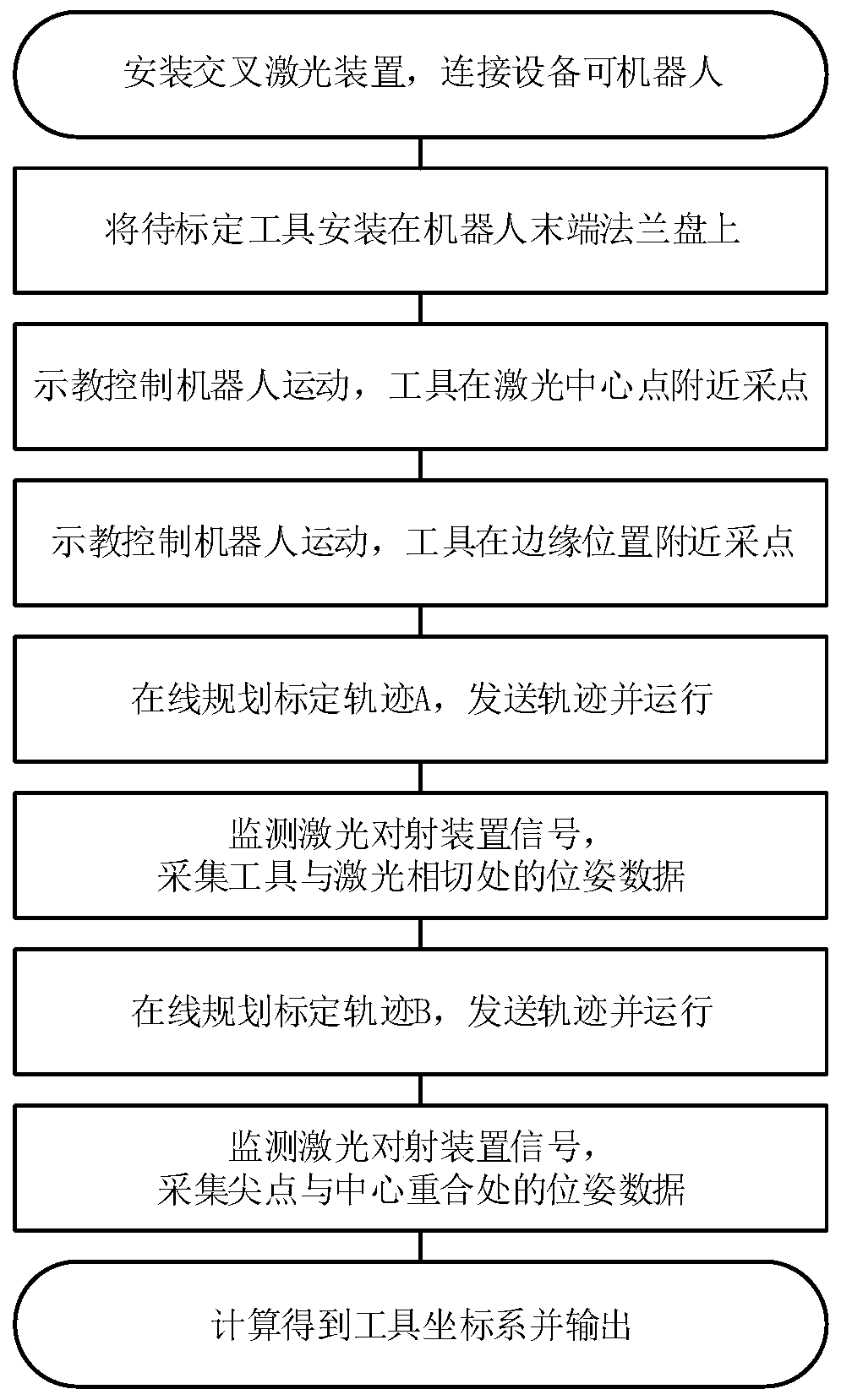
[0020] Embodiment 1: An automatic calibration method for a sharp-point rotary tool is provided, which includes the following steps:

[0021] (1) Install the cross laser shooting device in the working space of the robot, and connect the laser device and the robot motion control system through the calibration software.

[0022] (2) Clamp the tool to be calibrated at the end of the robot, control the movement of the robot so that the tool is near the center of the cross laser device and the edge of the measurement area of ​​the cross laser beam device, and record the end pose of the robot flange through software; control The robot changes its posture, and then makes the tool near the center of the cross laser beam, records the current robot flange end posture, repeats 3 times, and takes data in four different postures.

[0023] (3) After obtaining the key data, the calibration software plans the arc trajectory online and sends the trajectory to the robot motion control system to ...

Embodiment 2

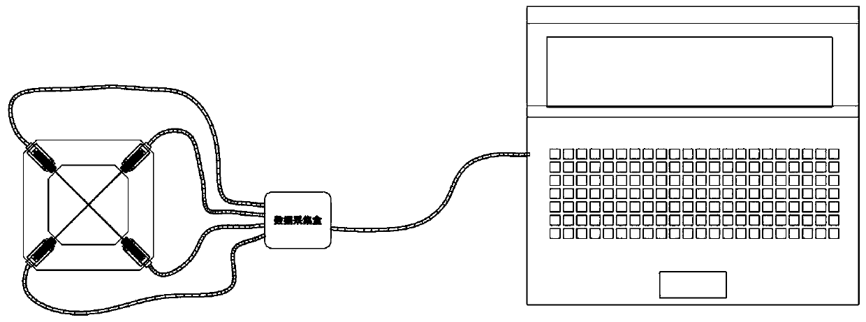
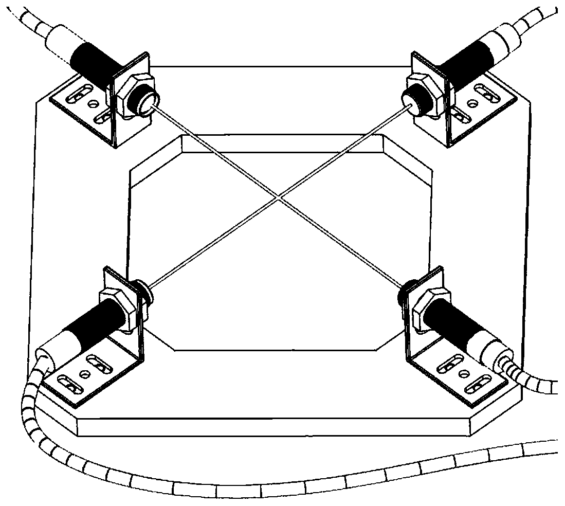
[0026] Embodiment two: figure 1 It shows the schematic diagram of the experimental connection of the cross-laser cross-firing device, which is mainly composed of three parts: 1. Cross-laser cross-firing device, 2. Data acquisition box, 3. PC-side software. figure 2 It shows the structure of the cross laser shooting device, which is mainly composed of two groups of laser shooting devices, each group includes a transmitting end and a receiving end, which are installed on the base through a right-angle bracket, so that the transmitting end and the receiving end are facing each other. The two laser beams are on the same plane and intersect at one point. . The inside of the data acquisition box is composed of two parts: 1. The power supply device, which provides a stable voltage for the laser shooting device. 2. AD conversion module, which converts the analog signal output by the laser shooting device into a digital signal and sends it to the software on the PC side.


PUM


Abstract

The invention discloses a cusp form revolution object tool calibration method for an industrial robot on the basis of a crossed laser beam. A crossed laser correlation device is connected with a robotmovement control system through calibration software, the calibration software obtains the tail end posture of a robot flange plate and plans a circular arc trajectory, and the trajectory is conveyedto the robot movement control system; in a process that a robot executes the circular arc trajectory, the calibration software monitors a signal of a laser beam and obtains the posture of the robot when the signal changes; the calibration software carries out on-line planning on a linear movement trajectory generated by movement along the axial line of a tool to be calibrated under different gestures, and then, the linear movement trajectory is conveyed to a robot movement controller to be executed; and when the signal suddenly changes, the posture of the tail end of the robot flange plate isobtained, and the position of the cusp of the tool is obtained through data under different postures. By use of the method, the automated calibration of a tool coordinate system is realized, and therefore, the problems of being complex in operation, high in cost, difficult in practical application and the like in tool calibration are solved.

Description

technical field [0001] The invention belongs to the technical field of industrial robot calibration, and in particular relates to a method for calibrating a cusp-type rotary tool of an industrial robot based on cross laser beams. Background technique [0002] With the development of industrial automation, traditional CNC machine tool processing can no longer meet complex and diverse processing and production. The application fields of industrial robots are becoming wider and wider, and the precision requirements for industrial robots are getting higher and higher. The accuracy of industrial robots can be improved through calibration. The calibration of industrial robots is mainly divided into two parts: body calibration and environmental calibration, of which environmental calibration is divided into tool calibration and workpiece calibration. This method mainly proposes a simple and effective automatic calibration method for sharp-point rotary tools. [0003] The ultimate ...

Claims


Application Information

Patent Timeline
IPC IPC(8): B25J9/16
CPCB25J9/1664
Inventor 马磊颜昌亚何姗姗李振瀚黄昆涛余娟
Owner WUHAN INSTITUTE OF TECHNOLOGY
Why Eureka
Try Eureka