Heat circulation drying box and drying method thereof

A technology of drying box and thermal cycle, applied in drying, drying machine, drying solid materials, etc., can solve the problems of heat energy loss, underutilization, environmental pollution, etc., and achieve the effect of saving heat energy and improving efficiency

Pending Publication Date: 2020-03-06
程冠皓 +2
View PDF0 Cites 5 Cited by
  • Summary
  • Abstract
  • Description
  • Claims
  • Application Information

AI Technical Summary

Problems solved by technology

[0002] At present, in order to preserve some crops, the dry storage method is usually used. At present, many workshops or self-employed people use ovens to dry crops. The existing ovens adjust the oven temperature by adjusting the exhaust air volume of the oven and setting the heater. To achieve the purpose of quickly drying agricultural products, however, there are still shortcomings in this drying method. The heat energy used in the drying process is discharged to the external environment through the exhaust pipe and is not fully utilized, resulting in environmental pollution and heat loss.

Method used


Image

  • Heat circulation drying box and drying method thereof
  • Heat circulation drying box and drying method thereof
  • Heat circulation drying box and drying method thereof

Examples


Embodiment 1

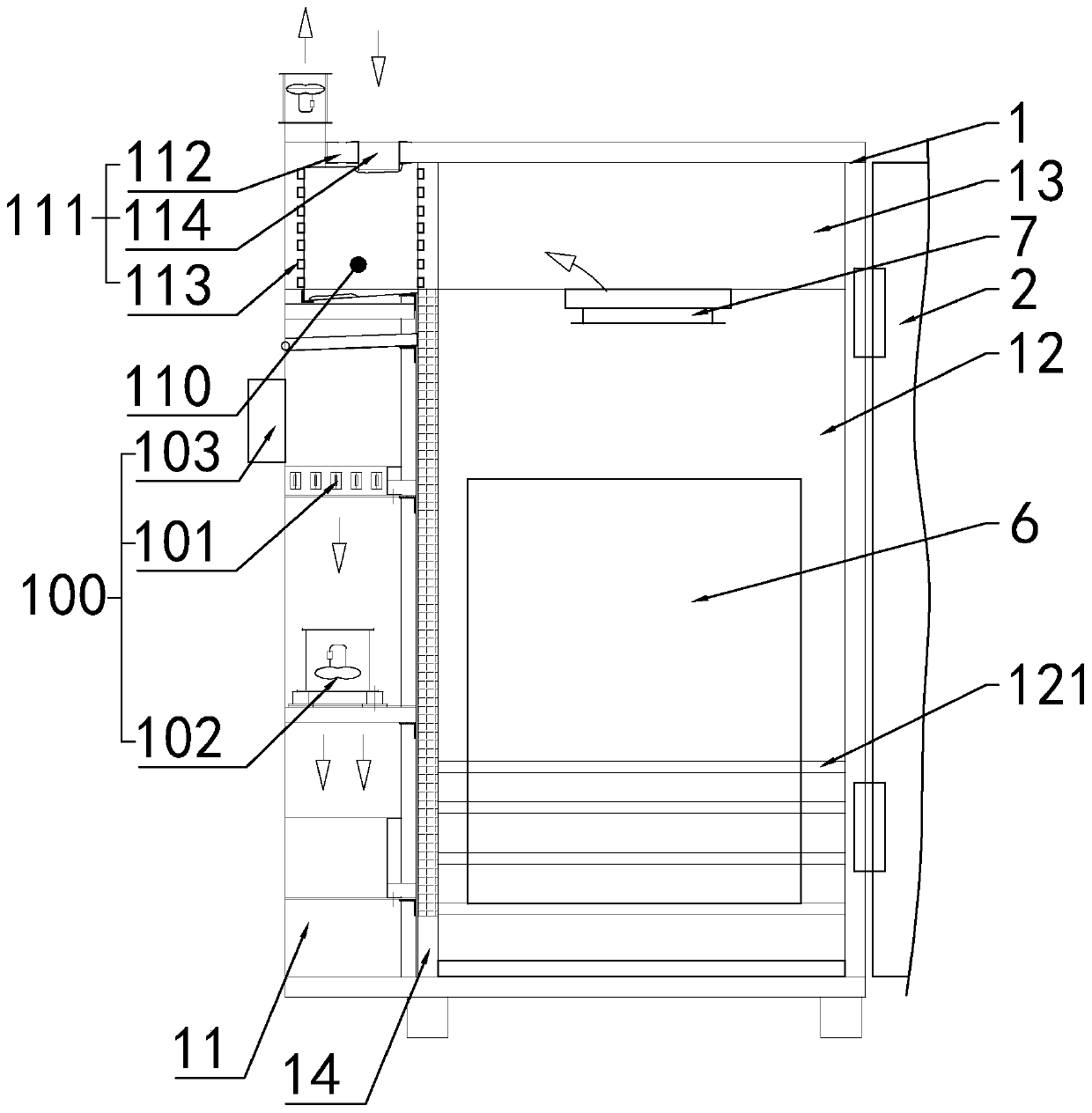
[0034] Such as figure 1 As shown, the present invention discloses a thermal cycle drying box, comprising a box body 1 and a box door 2, one side of the box door 2 is hinged to the box body 1; in a specific embodiment of the invention, the box body The inner cavity of 1 is provided with a heating chamber 11 and a drying chamber 12; a moisture box 13 is installed on the top of the box body 1 above the drying chamber 12; the moisture box 13 communicates with the drying chamber 12, and the heating chamber The side wall below 11 is provided with an air inlet 14 communicating with the drying chamber 12; a heating device 100 is arranged in the heating chamber 11, and the heating device 100 includes a heater 101, an axial flow fan 102 and Installed on the casing 1 for controlling the controller 103 of the heater 101 and the axial fan 102; the heater 101 and the axial fan 102 are installed on the inner wall of the heating chamber 11, and the output mouth downward; the controller 103 i...

Embodiment 2

[0036] Embodiment 2, the difference with the above-mentioned embodiment is

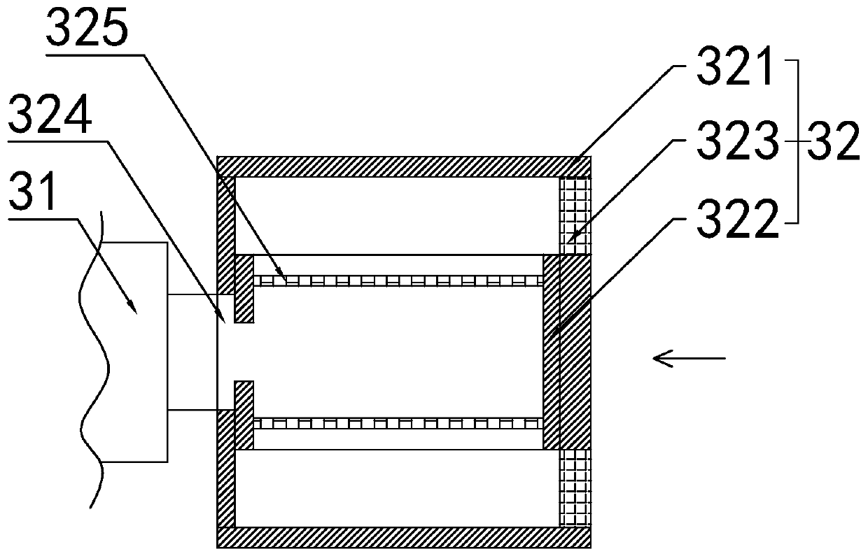
[0037] Such as figure 2 As shown, in a specific embodiment of the present invention, the heat exchange box 112 is provided with an air intake device 3 for sucking air into the heat exchange box 112; the air intake device 3 includes a No. 2 axial flow fan 31 and The activated carbon adsorption box 32 ; the output port of the No. 2 axial flow fan 31 communicates with the fresh air input port 114 ; the activated carbon adsorption box 32 is fixedly installed on the input port of the No. 2 axial flow fan 31 .

[0038] In a specific embodiment of the present invention, the activated carbon adsorption box 32 includes an activated carbon box 321, an activated carbon storage box 322, and a filter screen 323; air inlets are provided on both sides of the activated carbon box 321; The middle part of the side wall is provided with a transverse through hole 324, and the activated carbon box 321 communicates with ...

Embodiment 3

[0040] Embodiment 3, differs from the foregoing embodiments in that

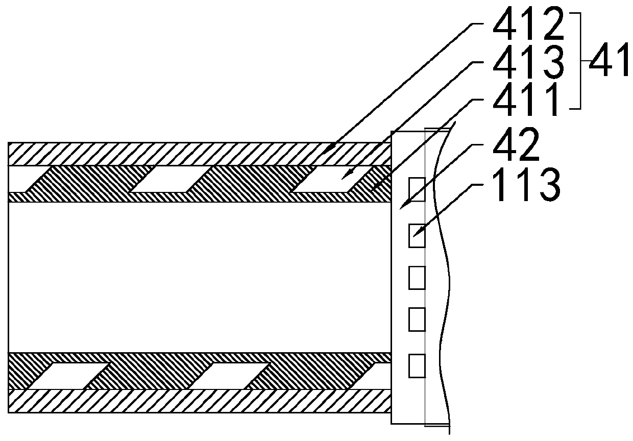
[0041] Such as image 3 As shown, in a specific embodiment of the present invention, a condensing device 4 is provided on the side wall of the box body 1; a vertical condensing pipe 41 and an air inlet box 42 of the condensing device 4, and the condensing pipe 41 includes an inner cylinder 411 and the outer cylinder 412 sleeved outside the inner cylinder 411, the outer wall of the inner cylinder 411 is provided with a spiral groove 413; connected.

[0042] Compared with the prior art, the beneficial effect brought by the present invention is: by being provided with a condensing device; the cooling device can condense the steam into water for collection, avoiding the pollution of the working environment caused by the direct discharge of hot steam, and ensuring the safety of the working environment clean.


PUM


Abstract

The invention relates to the technical field of drying, in particular to a heat circulation drying box and a drying method thereof. According to the technical scheme of the heat circulation drying boxand the drying method thereof, the heat circulation drying box comprises a box body and a box door, wherein one side of the box door is hinged with the box body; and the heat circulation drying box is characterized in that the inner cavity of the box body is provided with a heating cavity and a drying cavity, the top of the box body above the drying cavity is provided with a moisture box, the boxbody above the heating cavity is provided with a waste heat recovery device, and the waste heat recovery device comprises an energy recovery pump for recovering waste heat. According to the heat circulation drying box and the drying method thereof, the waste heat generated in the drying process is recovered by arranging the energy recovery pump, so that the effect of energy saving and emission reduction is realized; meanwhile, drying efficiency and drying effect are improved, and popularization is easy.

Description

technical field [0001] The invention relates to the technical field of drying, in particular to a heat circulation drying box and a drying method thereof. Background technique [0002] At present, in order to preserve some crops, the dry storage method is usually used. At this stage, many workshops or self-employed people use ovens to dry crops. The existing ovens adjust the oven temperature by adjusting the exhaust air volume of the oven and setting the heater. To achieve the purpose of quickly drying agricultural products, however, there are still shortcomings in this drying method. The heat energy used in the drying process is discharged to the external environment through the exhaust pipe and is not fully utilized, resulting in environmental pollution and heat energy loss. Contents of the invention [0003] Aiming at the deficiencies in the prior art, the object of the present invention is to provide an intelligent, energy-saving, high-efficiency thermal cycle drying o...

Claims


Application Information

Patent Timeline
Patent Type & Authority Applications(China)
IPC IPC(8): F26B11/14F26B11/18F26B21/00F26B21/06F26B21/08F26B25/00F26B25/04F26B25/12F26B25/16F26B25/18
CPCF26B11/14F26B11/18F26B21/001F26B21/003F26B21/004F26B21/06F26B21/083F26B21/086F26B25/00F26B25/008F26B25/04F26B25/12F26B25/16F26B25/185Y02P70/10
Inventor 程冠皓严洪吴立坤
Owner 程冠皓
Why Eureka
Try Eureka