Off-axis reflection free-form surface laser shaping system
A technology of off-axis reflection and laser shaping, applied in optics, optical components, instruments, etc., can solve problems such as difficult optimization, large amount of calculation, local minimum, etc., and achieve the effect of wide industrial application range and compact system structure
- Summary
- Abstract
- Description
- Claims
- Application Information
AI Technical Summary
Problems solved by technology
Method used
Image
Examples
Embodiment 1
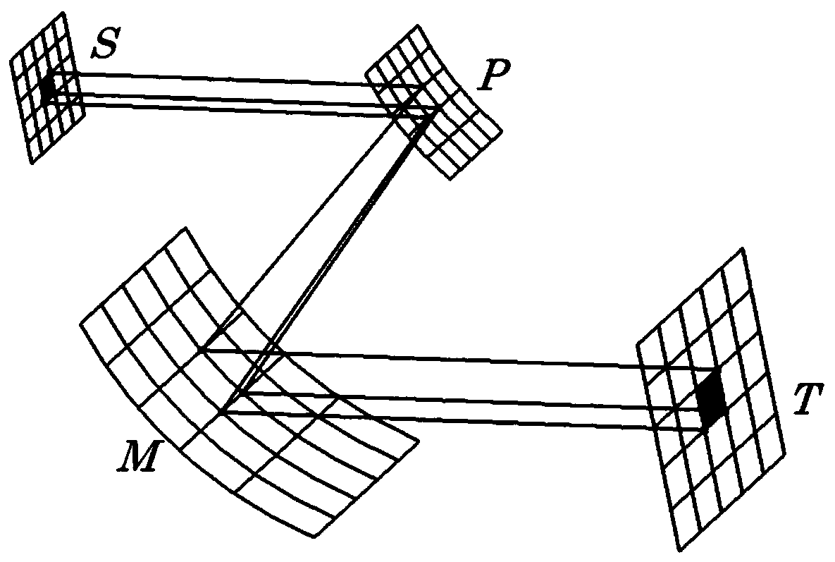
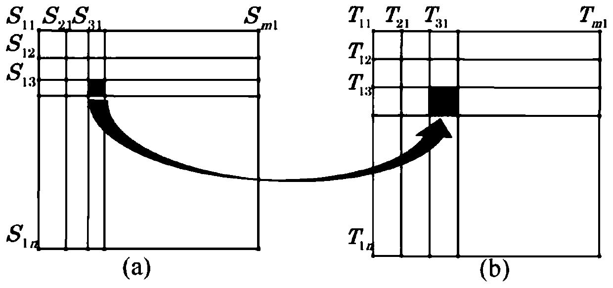
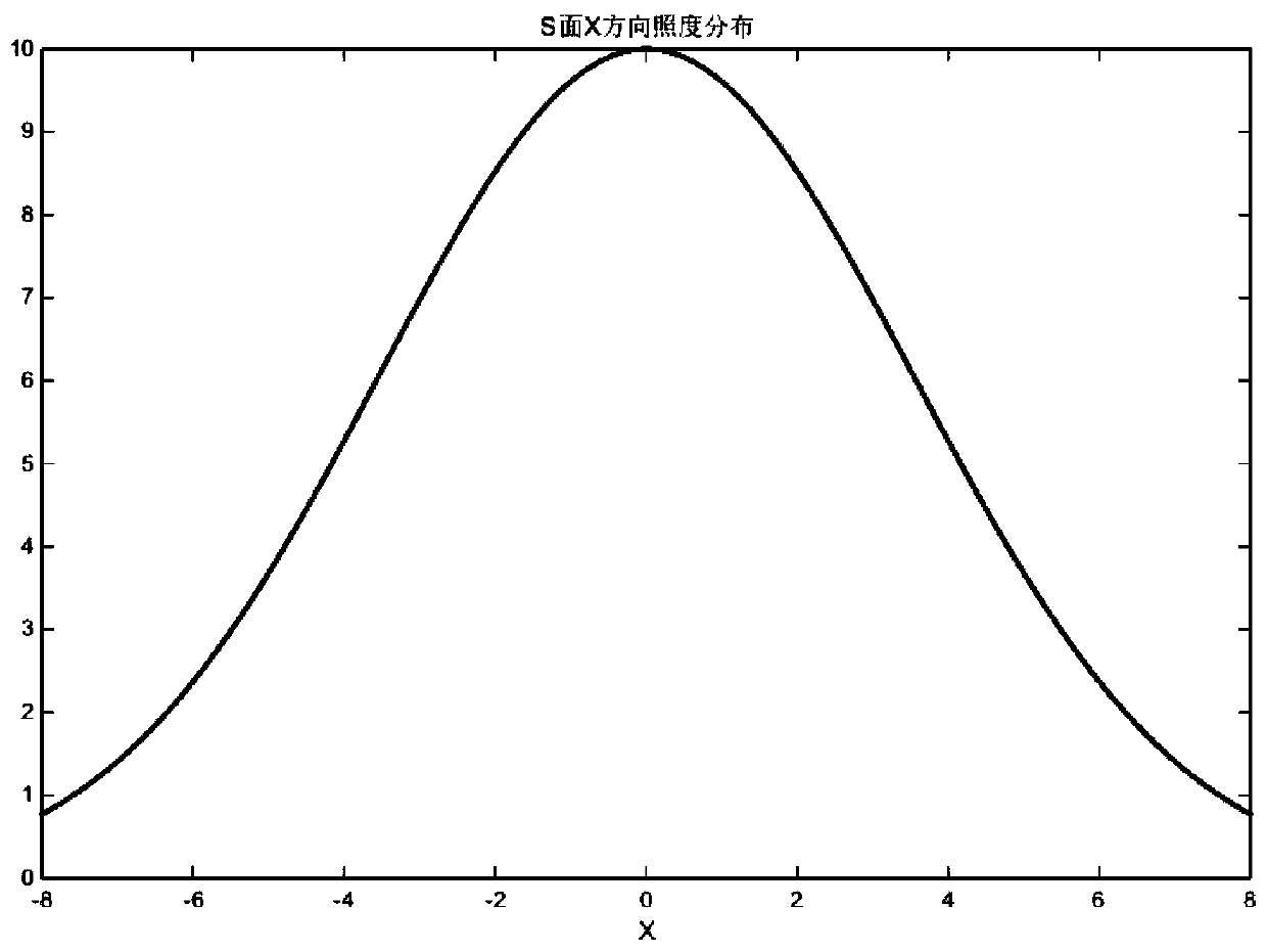
[0063] The specific implementation is as figure 1 As shown, the surface S is the cross-section of the incident laser beam, the light irradiance distribution on the cross-section is Gaussian distribution, the T surface is the target surface, P and M are two mirrors, and the surface shape of these two mirrors is a free-form surface. Therefore P and M constitute an off-axis reflective free-form surface system. The design principle of the laser shaping system is: divide the incident section S into M×N grids, each grid has equal energy, and divide the target surface T into M×N grids, and each grid is divided into equal areas. By designing an off-axis free-form surface reflection system composed of P and M, each sub-beam passing through the grid on the S surface is controlled, and after being reflected by P and M, it is incident on the corresponding grid on the target surface T. Since each sub-beam has equal energy, each grid on the target surface has an equal area, so that the ent...
Embodiment 2
[0086] Embodiment 2: adopt the plastic system designed by the method of embodiment 1
[0087] The input beam is a collimated laser beam, the beam is a square aperture, the size is 8mm×8mm, the irradiation target surface is 80mm×80mm, and the grid division number is 161×161. The shaping system designed according to the above method is as follows: Figure 7 , the irradiance as Figure 8 Shown: the uniformity of illuminance on the target surface reaches 91%, where the uniformity is the ratio of the average illuminance value to the maximum illuminance value on the target surface.
Embodiment 3
[0088] Embodiment 3: adopt the plastic system designed by the method of embodiment 1
[0089] Shape the square-aperture laser beam (the cross-sectional light intensity distribution is Gaussian distribution) into a uniformly distributed strip-shaped spot. Change the size of the target surface in the square uniform spot shaping system to 120mm×20mm, and keep the other parameters unchanged. A system designed using the above method such as Figure 9 As shown in (a), the illuminance distribution on the target surface is as follows Figure 9 (b) shown. It can be seen from the simulation results that the designed reflective shaping system can effectively shape the Gaussian distributed rectangular aperture laser beam into a long strip beam, the output spot size is 120mm×20mm, and the irradiance uniformity of the target surface is 94.57%.
PUM
 Abstract
Description
Claims
Application Information
 - R&D
- Intellectual Property
- Life Sciences
- Materials
- Tech Scout
- Unparalleled Data Quality
- Higher Quality Content
- 60% Fewer Hallucinations
Browse by: Latest US Patents, China's latest patents, Technical Efficacy Thesaurus, Application Domain, Technology Topic, Popular Technical Reports.
© 2025 PatSnap. All rights reserved.Legal|Privacy policy|Modern Slavery Act Transparency Statement|Sitemap|About US| Contact US: help@patsnap.com


