Built-in permanent magnet synchronous motor control method

A technology of permanent magnet synchronous motor and control method, which is applied in the direction of motor generator control, electronic commutation motor control, control system, etc., and can solve the problems of no real-time and accurate use of motor parameters, motor torque accuracy, motor operating efficiency, etc.

Active Publication Date: 2020-03-06
CRRC YONGJI ELECTRIC CO LTD
View PDF6 Cites 12 Cited by
  • Summary
  • Abstract
  • Description
  • Claims
  • Application Information

AI Technical Summary

Problems solved by technology

[0004] The invention solves the problem that the motor parameters are not used accurately and in real time in the existing permanent magnet synchronous motor control meth...

Method used


Image

  • Built-in permanent magnet synchronous motor control method
  • Built-in permanent magnet synchronous motor control method
  • Built-in permanent magnet synchronous motor control method

Examples


Embodiment Construction

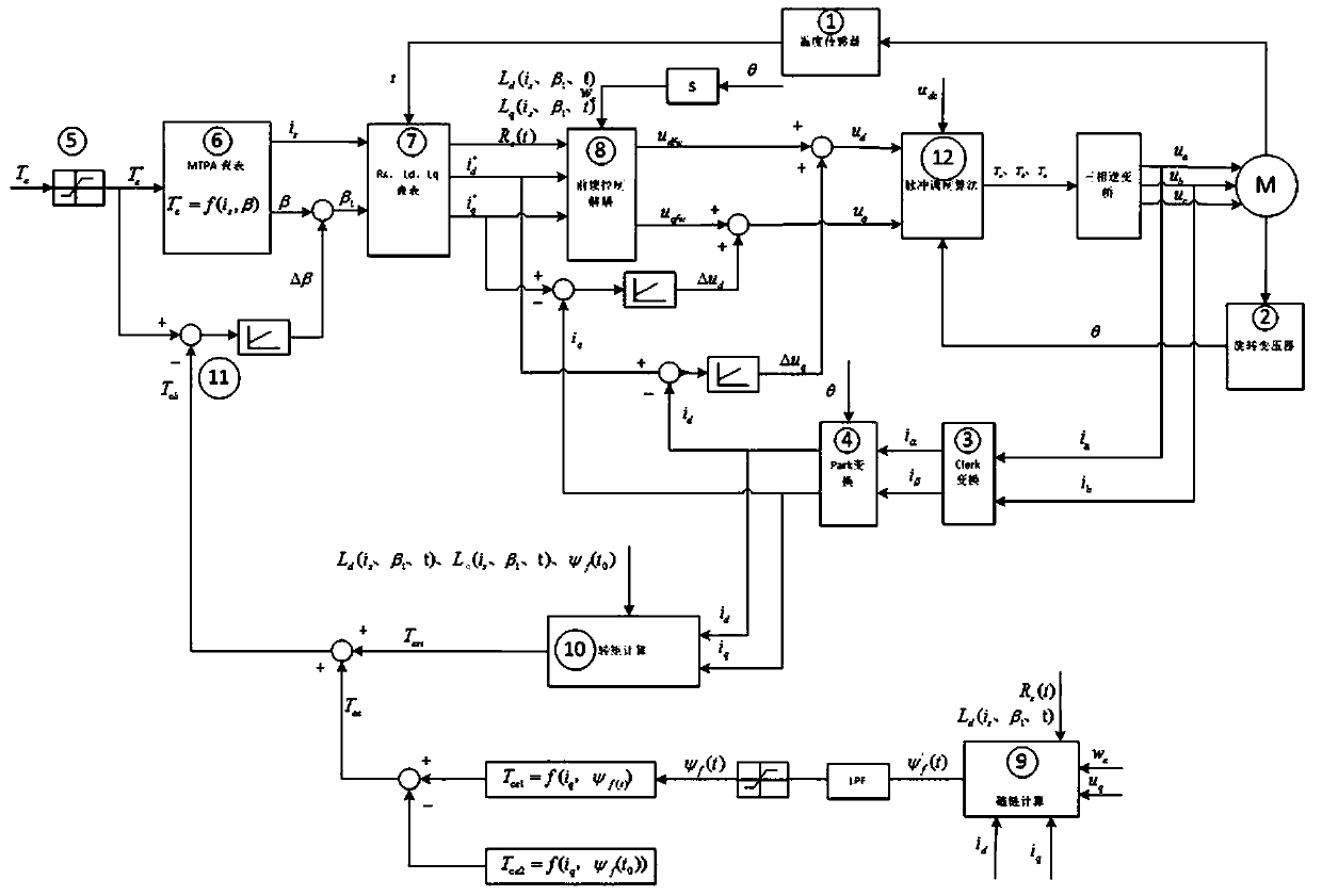
[0066] A control method for a built-in permanent magnet synchronous motor, which is divided into the following control modules (such as figure 1 Shown): temperature sensor module 1, resolver module 2, Clark transformation module 3, Park transformation module 4, torque command processing module 5, MTPA table lookup module 6, stator inductance and resistance parameter lookup table module 7, voltage calculation module , flux linkage calculation module 9, feedback torque calculation module 10, current vector angle adjustment module 11, pulse modulation module 12;

[0067] 1) Temperature sensor module

[0068] The temperature sensor is buried in the stator of the permanent magnet synchronous motor, and the real-time stator temperature t of the motor is collected by the temperature sensor.

[0069] 2) Resolver module

[0070] The resolver is installed on the permanent magnet synchronous motor, and the rotor position θ of the permanent magnet synchronous motor is acquired through t...


PUM


Abstract

The invention relates to a permanent magnet synchronous motor control method, in particular to a built-in permanent magnet synchronous motor control method. The problem that motor parameters are not accurately used in real time in an existing permanent magnet synchronous motor control method, so that the motor output torque precision and the motor operation efficiency are affected is solved. According to the control method, the influence of temperature change and the motor saturation effect on the motor parameters is considered online at the same time, and the accuracy of the parameters of themotor at each working point is improved. According to the invention, based on the motor temperature t, the current amplitude is, the current vector angle beta on-line real-time table lookup and the MTPA real-time table lookup on the feedforward channel, the flux linkage is calculated in real time by using the flux linkage calculation model on the feedback channel, so that rotor temperature detection equipment is omitted; and d-axis current and q-axis current are redistributed by utilizing an output result of a torque closed loop, so that the permanent magnet synchronous motor is maintained tooperate according to an MTPA track, and the heating and loss of the motor are reduced.

Description

technical field [0001] The invention relates to a control method for a permanent magnet synchronous motor, in particular to a control method for a built-in permanent magnet synchronous motor. Background technique [0002] Built-in permanent magnet synchronous motors are gradually and widely used in urban transportation fields such as guide rail cars due to their advantages such as high power density, high power factor, and high overload capacity. High efficiency performance is very important and is the key to measuring the performance of traction system. However, the motor parameters of the built-in permanent magnet synchronous motor are greatly affected by the saturation effect of the stator core and the temperature change. One of the most important factors affecting the torque accuracy of the built-in permanent magnet synchronous motor on the guide rail tram is that the motor is running. and the motor parameter L caused by the change of stator current d , L q , R s , Ψ...

Claims


Application Information

Patent Timeline
IPC IPC(8): H02P21/00H02P21/14H02P21/18H02P21/20H02P21/22
CPCH02P21/0003H02P21/14H02P21/18H02P21/20H02P21/22
Inventor 柴璐军张瑞峰杨高兴贺志学梁海刚詹哲军李岩
Owner CRRC YONGJI ELECTRIC CO LTD
Why Eureka
Try Eureka