
Wireless optical communication system with double rotating ends

A technology of wireless optical communication and rotating end, applied in the field of wireless optical communication, can solve the problems of poor confidentiality performance, reduced communication reliability, increased attenuation coefficient, etc., and achieves the effect of satisfying sensitivity requirements, small spot area change, and ensuring high-speed communication.

Pending Publication Date: 2020-03-06
NO 34 RES INST OF CHINA ELECTRONICS TECH GRP
View PDF0 Cites 3 Cited by
  • Summary
  • Abstract
  • Description
  • Claims
  • Application Information

AI Technical Summary

Problems solved by technology

For signals that require high-speed transmission, the communication reliability is also reduced due to the increase of the attenuation coefficient
On the other hand, the use of electric slip rings to transmit information has very poor confidentiality and security cannot be guaranteed
In addition, the electric slip ring is used to transmit information, and its anti-electromagnetic interference ability is very poor, especially under the condition of high-speed rotation at both ends, the electric slip ring is not suitable for high-speed signal transmission.
[0003] Optical fiber slip rings have high requirements on installation conditions and installation accuracy. For example, the axial deviation must not exceed tens of microns, so the cost of optical fiber slip rings is very high.
And after the optical fiber slip ring product leaves the factory, its structure is fixed, the distance between the two rotating ends is fixed by the external structure of the optical fiber slip ring, the distance between the two rotating ends is difficult to adjust, so that the use of the optical fiber slip ring affected by

Method used


Image

  • Wireless optical communication system with double rotating ends
  • Wireless optical communication system with double rotating ends

Examples


Embodiment Construction

[0030] In order to make the technical solution of the present invention clearer, the present invention will be further described in detail below in conjunction with the embodiments and accompanying drawings.

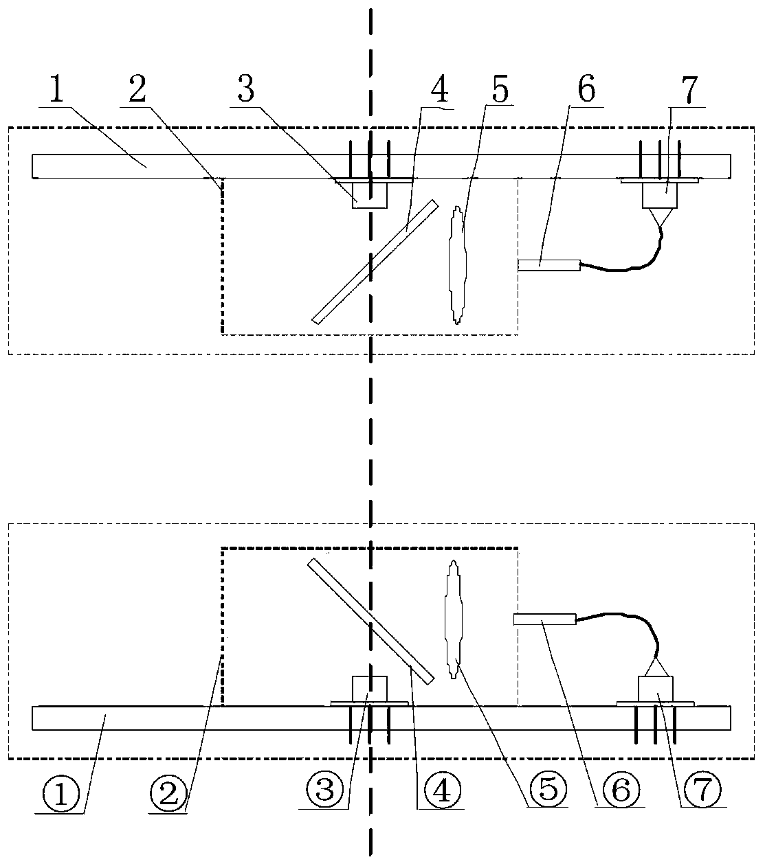
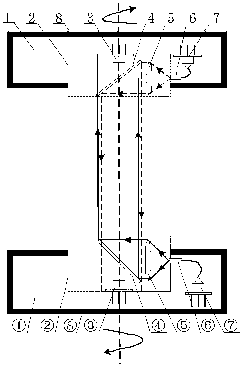
[0031] The internal structure of the embodiment of the wireless optical communication system with double rotating ends is as follows: figure 1 As shown, including the A rotating end with the same structure ( figure 1 The upper dotted line box in ) and the rotating end of B ( figure 1 The lower dotted line box in ), A rotating end includes a circuit board 1, a laser 7, a coupling fiber 6, a collimator lens 5, a dichroic filter 4, an APD detector 3 and a structure 2, and the structure 2 is fixed on the circuit board 1 on. Such as figure 2 As shown in the upper part of the figure, the shell 8 of the rotating end A is fixedly connected with its structural part 2, the circuit board 1 of the rotating end A and its laser 7, coupling fiber 6, collimating lens 5, dichroic sep...


PUM


Abstract

The invention relates to a wireless optical communication system with double rotating ends, which comprises a rotating end A and a rotating end B with the same structure, a laser is fixedly arranged on a circuit board, and the circuit board controls the rotating ends to generate laser signals to enter a coupling optical fiber. The coupling optical fiber introduces an optical signal into the collimating lens to be changed into a parallel light beam, the parallel light beam enters the two-way color separation sheet to be reflected and enters the APD detector at the opposite end in the directionof the rotating shaft, and the optical signal is converted into an electric signal and transmitted to the circuit board at the local end to be processed. The lasers at the A end and the B end generatelasers with the wavelength being X nm and Y nm respectively, the two-way color separation part is fixedly installed on the structural part, the center of the two-way color separation part is locatedon the rotating shaft center line, and the surface normal and the rotating shaft center line form a 45-degree angle. And the two-way color separation sheet at the end A reflects the laser of Xnm and transmits the laser of Ynm. And the two-way color separation sheet at the B end reflects the laser of Ynm and transmits the laser of Xnm. The center lines of rotating shafts of the AB rotating ends coincide. Reliable high-speed communication can be achieved when the communication distance between the two ends changes from 5 mm to 500 mm.

Description

technical field [0001] The invention relates to the technical field of wireless optical communication, in particular to a wireless optical communication system with double rotating ends. The system realizes non-contact real-time optical communication with double rotating ends. Background technique [0002] Some instruments with rotating structures sometimes need to transmit a large amount of information from one rotating end to the other rotating end. Traditional methods mainly use electrical slip rings or optical fiber slip rings to connect the two rotating ends. The electric slip ring is mainly used to transmit electric signals, and adopts a contact-type rotary connection method, and the ring body of the electric slip ring is in contact with the contacts of the electric slip ring. Due to the effect of contact friction in the connection of the electric slip ring, with the accumulation of working time, the wear and tear of the electric slip ring ring body and the electric s...

Claims


Application Information

Patent Timeline
Patent Type & Authority Applications(China)
IPC IPC(8): H04B10/25H04B10/50H04B10/60
CPCH04B10/503H04B10/60
Inventor 崔新旭罗广军何晓垒蒋蔚裘晓磊钱阳卫斌
Owner NO 34 RES INST OF CHINA ELECTRONICS TECH GRP
Learn More