
Continuous carbon fiber storage battery electrolyte injection equipment

A storage battery and carbon fiber technology, which is applied to battery components, circuits, electrical components, etc., can solve the problems of low efficiency of manual liquid injection, and achieve the effect of improving processing efficiency and improving work efficiency

Pending Publication Date: 2020-03-10
GUANGZHOU ZHUOYUE POWER NEW ENERGY CO LTD
View PDF0 Cites 0 Cited by
  • Summary
  • Abstract
  • Description
  • Claims
  • Application Information

AI Technical Summary

Problems solved by technology

[0005] The purpose of the present invention is to provide a continuous carbon fiber battery liquid injection equipment to solve the problem of low efficiency of manual liquid injection

Method used


Image

  • Continuous carbon fiber storage battery electrolyte injection equipment
  • Continuous carbon fiber storage battery electrolyte injection equipment
  • Continuous carbon fiber storage battery electrolyte injection equipment

Examples


Embodiment Construction

[0035] The following is further described in detail through specific implementation methods:

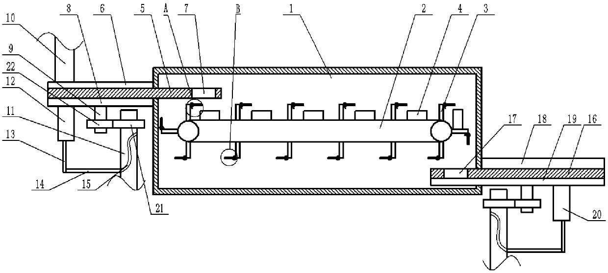
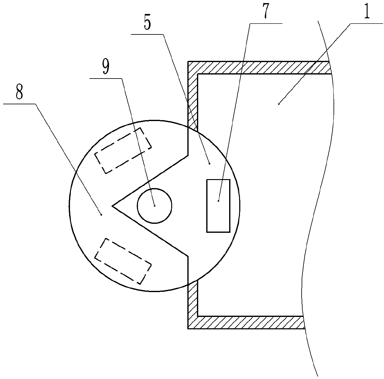
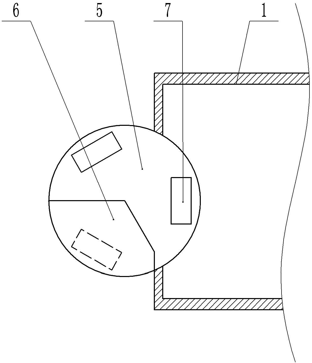
[0036] The reference signs in the drawings of the description include: vacuum chamber 1, conveyor belt 2, separator 3, battery 4, first turntable 5, first cover plate 6, first through hole 7, first support plate 8, connecting shaft 9 , feeding cylinder 10, rotating shaft 11, first pumping cylinder 12, pole 13, guide rod 14, cam groove 15, second turntable 16, second through hole 17, second cover plate 18, second support plate 19, The second pumping cylinder 20, incomplete gear 21, gear 22, liquid outlet pipe 23, liquid outlet nozzle 24, inserting plate 25, main pipe 26, liquid storage tank 27.

[0037] like figure 1 As shown, a continuous carbon fiber battery liquid injection equipment includes a frame, on which a vacuum chamber 1 is fixed. The vacuum chamber 1 is provided with a transmission mechanism for transmitting the battery 4. The transmission mechanism includes a conveyor be...


PUM


Abstract

The invention belongs to the field of battery processing, and specifically discloses continuous carbon fiber storage battery electrolyte injection equipment. The equipment comprises a rack, and is characterized in that a vacuum chamber is fixed on the rack, a feeding mechanism is arranged above the feeding end of a conveying mechanism on the rack, a discharging mechanism is arranged below the discharging end of the conveying mechanism on the rack, and the rack is provided with a first driving mechanism used for driving the feeding mechanism to operate and a second driving mechanism used for driving the discharging mechanism to operate; the rack is further provided with an electrolyte injection mechanism used for injecting an electrolyte into the battery, the electrolyte injection mechanismincludes an electrolyte storage tank which is fixed on the rack and used for storing the electrolyte; the feeding mechanism includes a first rotary plate rotatably connected to the rack, three identical feeding areas are evenly distributed in the circumferential direction on the rotary plate, the discharging mechanism includes a second rotary plate rotatably connected to the rack, and three identical discharging areas are evenly distributed in the circumferential direction on the second rotary plate. By adopting the scheme of the invention, the problem of low efficiency of manual electrolyteinjection can be solved.

Description

technical field [0001] The invention belongs to the field of processing carbon fiber storage batteries, and in particular relates to a continuous liquid injection device for carbon fiber storage batteries. Background technique [0002] Existing battery plate substrates are mainly made of metal or alloy materials. The requirements for the substrate are good conductivity and good corrosion resistance. For example, lead-acid batteries use lead-antimony alloys, and valve-regulated sealed lead-acid batteries use lead-calcium-tin-aluminum alloys or Lead-antimony-cadmium alloy and the above battery alloys need to contact 40% sulfuric acid aqueous solution (ie electrolyte) to work normally, and acid has a corrosive effect on the above materials, and the failure of the battery due to corrosion is an important factor that limits the life of the battery. [0003] In order to solve the above problems, carbon fiber batteries came into being. Carbon fiber batteries use AGM (glass fiber s...

Claims


Application Information

Patent Timeline
IPC IPC(8): H01M2/36H01M50/60
CPCH01M50/60Y02E60/10
Inventor 何幸华黎少伟李政文何可立马俊
Owner GUANGZHOU ZHUOYUE POWER NEW ENERGY CO LTD
Learn More