Electric transportation vehicle with clamping, overturning and rotating mechanisms
A technology of electric pallet truck and rotating mechanism, which is applied in the direction of lifting device, etc., which can solve the problems of non-direct docking installation, no workpiece turnover, laborious transportation, etc., and achieve the effect of simple structure, easy operation and high universality
- Summary
- Abstract
- Description
- Claims
- Application Information
AI Technical Summary
Problems solved by technology
Method used
Image
Examples
Embodiment 1
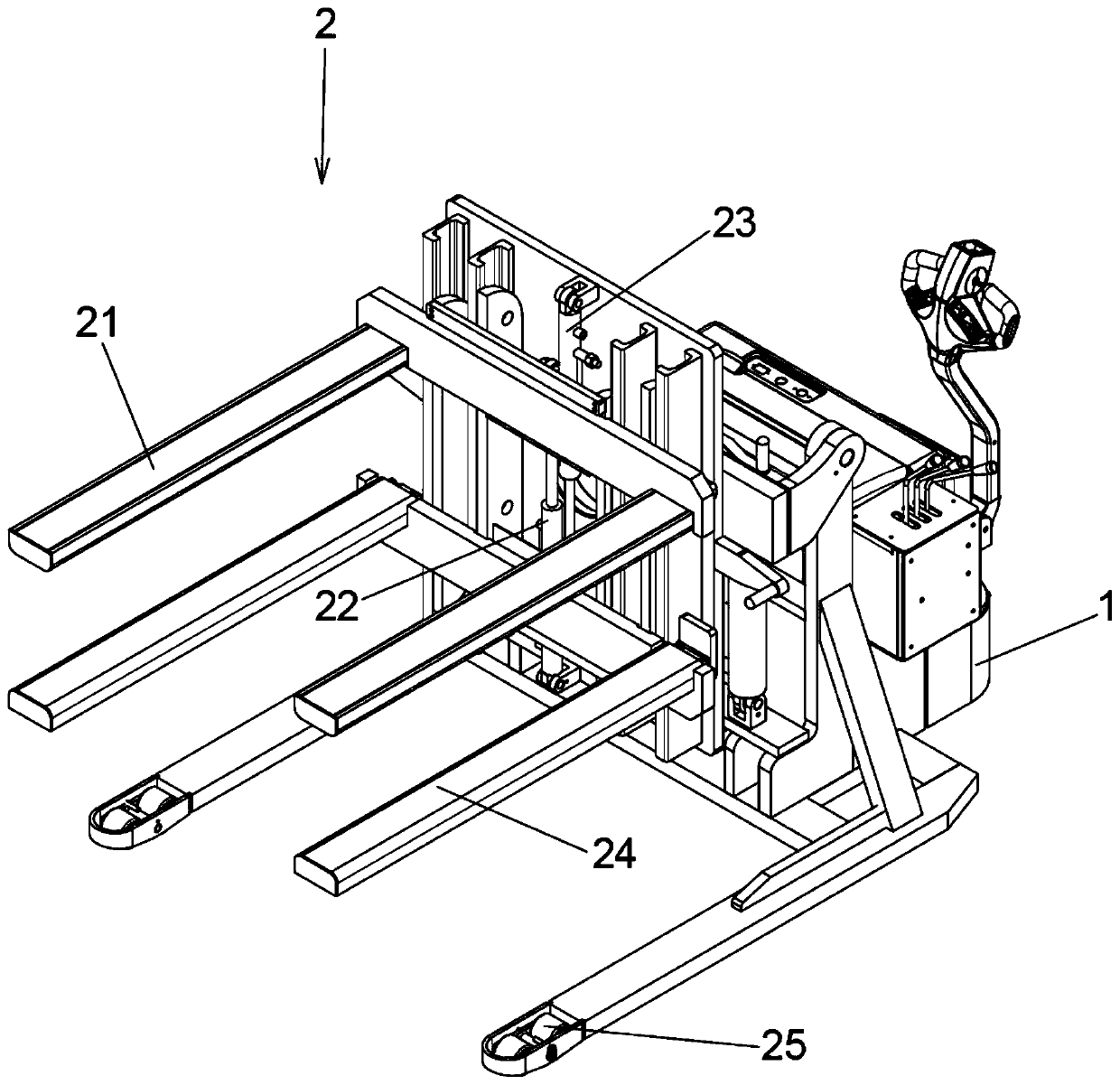
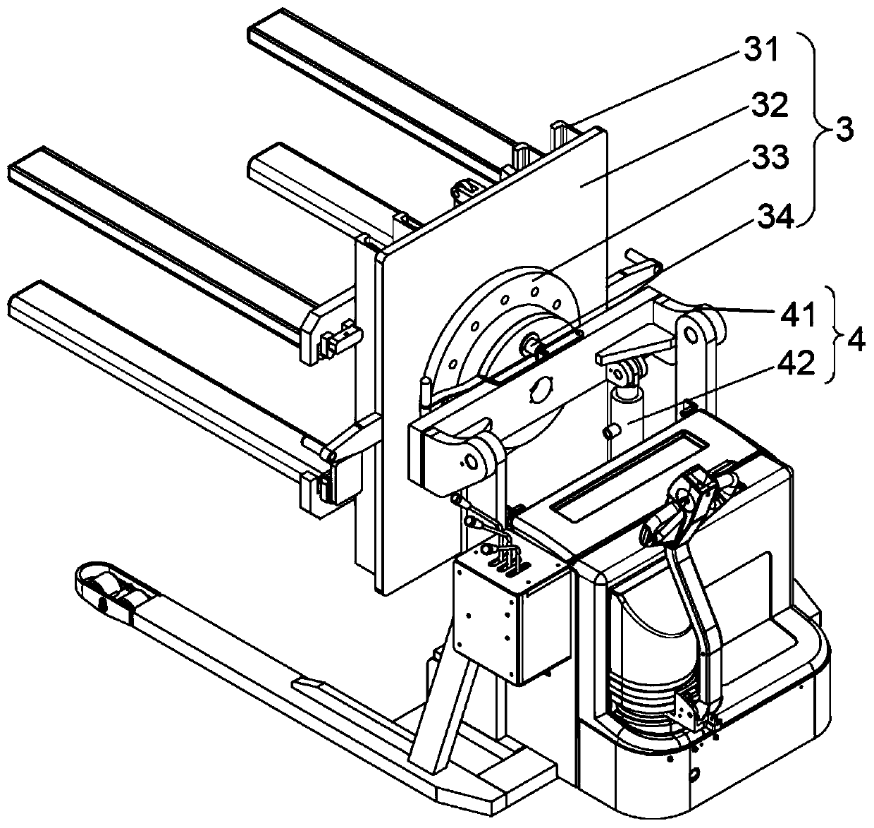
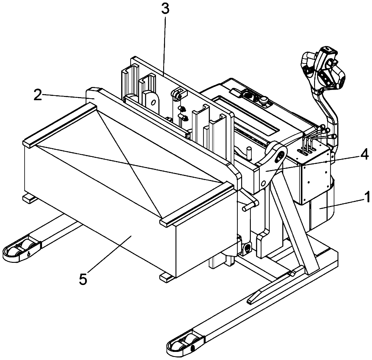
[0030] Embodiment 1: If the position adjustment of each surface of the workpiece 5 is to be realized to facilitate the processing of each surface, the clamping arm one 21 and the clamping arm two 24 of the clamping mechanism 2 can be close to both sides of the workpiece 5, and then clamped The piston rods of cylinder one 22 and clamping cylinder two 23 are retracted, so that clamp arm one 21 and clamp arm two 24 are close to each other, and the workpiece 5 is clamped. The tightening mechanism 2 turns over 90° to a horizontal state, and the workpiece 5 can be turned from a horizontal position to a vertical state. Opening the rotating locking mechanism 34 on the rotating mechanism 3 can rotate the workpiece 360° around the center of rotation by manpower, hydraulic pressure, and electrical control.
Embodiment 2
[0031] Embodiment 2: For the workpiece 5 that is inconvenient to hoist, the pallet 6 can be installed on the workpiece 5 to realize transshipment. For the working conditions of automatically rotating the pallet 6 such as hydraulic pressure and electricity, specifically, the clamping oil cylinder 22 and the clamping oil cylinder The piston rods of the second 23 are all extended, so that the distance between the first clamp arm 21 and the second clamp arm 24 becomes larger appropriately, and then the pallet 6 is manually installed on the upper surface of the workpiece 5, and the first clamp arm 21 and the second clamp arm 24 penetrate into the workpiece respectively. In the fork hole of the pallet 6, retract the piston rods of the clamping cylinder 1 22 and the clamping cylinder 2 23, so that the clamping arm 1 21 and the clamping arm 2 24 can stably clamp the workpiece 5, and control the rotating mechanism 3 around the center of rotation Rotate 180°, now the tray 6 is located at...
Embodiment 3
[0032]Embodiment 3: For the workpiece 5 that is inconvenient to hoist, the pallet 6 can be installed on the workpiece 5 to realize the transfer. For the working condition of manually rotating the pallet 6, specifically, the pistons of the clamping cylinder one 22 and the clamping cylinder two 23 The rods are all elongated, so that the distance between clamp arm 1 21 and clamp arm 2 24 becomes larger appropriately, and then the tray 6 is manually installed on the upper surface of the workpiece 5, and clamp arm 1 21 and clamp arm 2 24 respectively penetrate into the forks of the pallet 6 In the hole, retract the piston rods of clamping cylinder 1 22 and clamping cylinder 2 23, thereby stably clamping the workpiece 5, and the turning cylinder 42 pushes the turning frame 41, so that the rotating mechanism 3 and the clamping mechanism 2 turn over 90° To the horizontal state, the pallet 6 is vertically positioned at the rear of the workpiece 5, and the rotary locking mechanism 34 on ...
PUM
 Abstract
Description
Claims
Application Information
 - R&D
- Intellectual Property
- Life Sciences
- Materials
- Tech Scout
- Unparalleled Data Quality
- Higher Quality Content
- 60% Fewer Hallucinations
Browse by: Latest US Patents, China's latest patents, Technical Efficacy Thesaurus, Application Domain, Technology Topic, Popular Technical Reports.
© 2025 PatSnap. All rights reserved.Legal|Privacy policy|Modern Slavery Act Transparency Statement|Sitemap|About US| Contact US: help@patsnap.com


