Multifunctional water pump

A multi-functional, water pump technology, applied in the direction of pumps, pump devices, pump components, etc., can solve the problems of impeller damage of power pumps, shorten the service life of power pumps, etc., and achieve the effects of low cavitation, reduced cost of accessories, and reduced maintenance.

Active Publication Date: 2020-03-13
江苏高群节能科技有限公司
View PDF12 Cites 3 Cited by
  • Summary
  • Abstract
  • Description
  • Claims
  • Application Information

AI Technical Summary

Problems solved by technology

[0005] Although this siphon device has the advantages of high efficiency and energy saving, in the actual use process, there will be impurities such as sediment in the pumped water source, and the sediment will enter the power pump with the water flow, which will easily cause damage to the impeller of the power pump. , shorten the service life of the power pump

Method used


Image

  • Multifunctional water pump
  • Multifunctional water pump
  • Multifunctional water pump

Examples


Embodiment 1

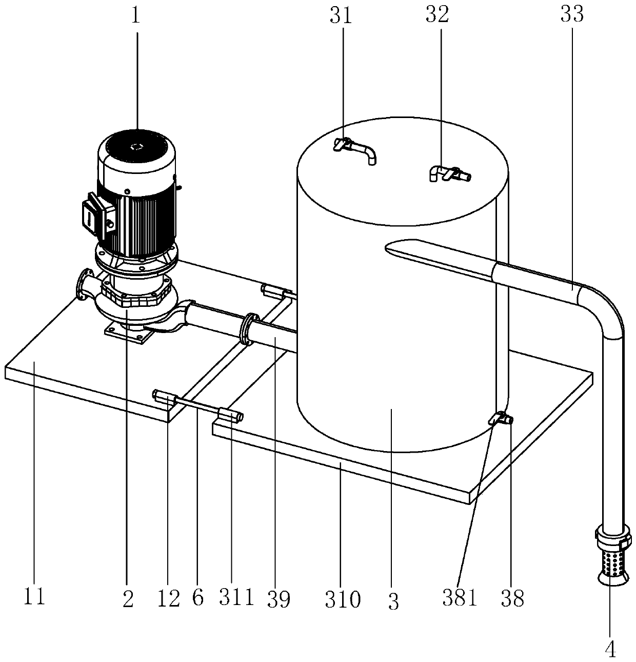
[0053] Embodiment 1: a kind of multifunctional water pump, as figure 1 As shown, it includes a drive motor 1, a pump body 2, and a siphon tank 3.

[0054] Such as figure 1 As shown, the siphon tank 3 is cylindrical. In addition, the siphon tank 3 is not limited to a cylindrical shape, and may also be other columnar structures. The top surface of the siphon tank 3 is provided with an exhaust valve 31 and a water injection pipe 32. Under initial conditions, water is injected into the siphon tank 3 through the water injection pipe 32, and the air in the siphon tank 3 is discharged through the exhaust valve 31, thereby maintaining internal and external air pressure. balance.

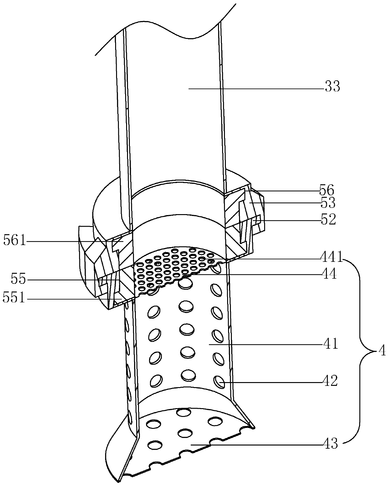
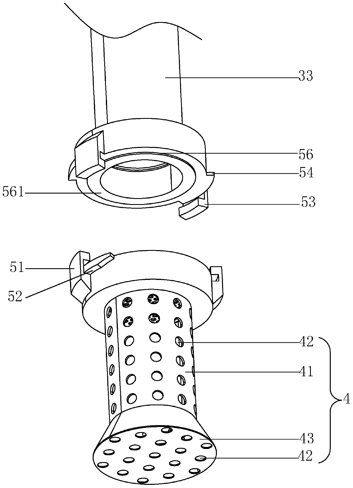
[0055] Siphon tank 3 is provided with water inlet pipe 33 near the position of its top, and water inlet pipe 33 is communicated with siphon tank 3 along the tangential direction of siphon tank 3, and water inlet pipe 33 adopts hard metal material to make. One end of the water inlet pipe 33 facing away fro...

Embodiment 2

[0074] Embodiment 2: a kind of multifunctional water pump, as Figure 10 and 11 As shown, the difference from Implementation 1 is that the bottom wall of the siphon tank 3 is provided with a sewage discharge tank 71, the sewage discharge tank 71 passes through the central axis of the siphon tank 3, and two spiral extruding rods 73 are arranged in the sewage discharge tank 71. Two spiral extruding rods 73 are arranged symmetrically about the axis of siphon tank 3, and sewage discharge pipes 72 are provided on the two side walls of siphon tank 3, and the opposite ends of the two spiral extruding rods 73 extend into corresponding sewage discharge pipes 72 respectively, and the sewage discharge A purge valve 76 is provided on the pipe 72 .

[0075]The opposite ends of the two spiral extruding rods 73 are provided with a first bevel gear 74, and the bottom end of the rotating shaft 34 is provided with a second bevel gear 75, and the second bevel gear 75 meshes with the two first b...


PUM


Abstract

The invention discloses a multifunctional water pump, belongs to the technical field of water pumps, and aims at providing a water pump system long in service life. According to the technical scheme,the multifunctional water pump is characterized by comprising a driving motor, a pump body and a siphoning tank; a water inlet of the pump body communicates with the bottom of the siphoning tank, anda water inlet pipe is arranged at the top of the siphoning tank; and a filtering device is arranged at the end, back to the siphoning tank, of the water inlet pipe, the filtering device comprises a filtering barrel, and a plurality of first filtering holes are formed in the periphery of the filtering barrel. According to the water pump, a fluid modified line volute low abrasion technology, a three-dimensional flow impeller, impeller nanoscale precision grinding, volute moving along with impellers and other high and new technologies are adopted to reduce abrasion of related parts, the failure rate is reduced, and maintenance is reduced; the operation stability and reliability of a pump set are improved, and the service life is prolonged; the optimized water pump efficiency is greatly improved compared with traditional method design, the multifunctional water pump replaces a traditional old non-sealed self-priming pump, and the energy saving rate of the technically improved water pump can reach 15% to 60%.

Description

technical field [0001] The invention relates to the technical field of water pumps, in particular to a multifunctional water pump. Background technique [0002] A water pump is a machine that transports or pressurizes a liquid. It transmits the mechanical energy of the prime mover or other external energy to the liquid to increase the energy of the liquid. It is mainly used to transport liquids including water, oil, acid and alkali, emulsion, and suspoemulsion. It can also transport liquid, gas mixture and liquid containing suspended solids; the technical parameters to measure the performance of the pump include flow rate, suction lift, head, shaft power, water power, efficiency, etc.; according to different working principles, it can be divided into It is a volumetric water pump, a vane pump, etc.; a volumetric pump uses the volume change of its working chamber to transfer energy; a vane pump uses the interaction between rotating blades and water to transfer energy, and the...

Claims


Application Information

Patent Timeline
Patent Type & Authority Applications(China)
IPC IPC(8): F04D13/06F04D29/00F04D29/70F04F10/00
CPCF04D13/06F04D29/007F04D29/708F04F10/00
Inventor 赵彦成黄忠军
Owner 江苏高群节能科技有限公司
Why Eureka
Try Eureka