A magnetic field modulated permanent magnet linear generator with composite armature structure

A permanent magnet linear and magnetic field modulation technology, which is applied in the shape/style/structure of winding conductors, electrical components, electromechanical devices, etc., which can solve the requirement of improving the comprehensive performance of linear generators, and it is difficult to obtain thrust characteristics and dynamic performance. Motor scheme and other issues

Active Publication Date: 2020-10-20
HEFEI UNIV OF TECH
View PDF1 Cites 0 Cited by
  • Summary
  • Abstract
  • Description
  • Claims
  • Application Information

AI Technical Summary

Problems solved by technology

However, the above motor types are subject to complex constraints among performance parameters, and it is difficult to obtain a motor solution that can take into account both...

Method used


Image

  • A magnetic field modulated permanent magnet linear generator with composite armature structure
  • A magnetic field modulated permanent magnet linear generator with composite armature structure
  • A magnetic field modulated permanent magnet linear generator with composite armature structure

Examples


Embodiment 1

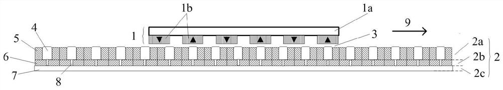
[0033] Embodiment 1: as figure 1 As shown, a magnetic field modulation permanent magnet linear generator with a compound armature structure is composed of a secondary 1, a primary armature 2, and an air gap 3 between the primary armature 2 and the secondary 1; the secondary is composed of The yoke plate 1a and the permanent magnet array 1b are composed; and the primary armature 2 is provided with a multi-layer composite structure composed of a modulation layer 2a, an air core winding layer 2b and an iron core layer 2c.

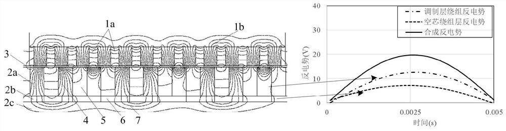
[0034] The modulation layer 2a is the upper layer, including the magnetic modulation block 4 and the modulation layer winding 5 . The magnetic adjustment block 4 adopts high magnetic permeability material and is arranged equidistantly along the moving direction of the motor. Number of pole pairs p of secondary 1 permanent magnet array 1b 1 , the number Z of the modulation block 4 and the pole pair number p of the traveling wave magnetic field generated by th...

Embodiment 2

[0040] Embodiment 2: as Figure 4a As shown, the difference from Embodiment 1 is that the side of the magnetic adjustment block 4 facing the air gap 3 is chamfered, which can obtain the same electromagnetic effect as the rounded corner treatment method, effectively suppressing the positioning force of the motor, but the process Implementation is simpler. Distance and angle α of chamfer 11 1 and alpha 2 Choose according to the specific number of poles and slots. The distance of the chamfer 11 should not be too large, otherwise the thrust of the motor will drop rapidly.

Embodiment 3

[0041] Embodiment 3: as Figure 4b As shown, the difference from Embodiment 1 and Embodiment 2 is that the modulation block 4 cuts out a groove shape with a wide top and a narrow bottom on the side facing the air gap 3 to form trapezoidal small teeth 12 . The uniform trapezoidal small teeth 12 can alleviate the sudden change of the motor air-gap flux permeability, thereby suppressing the positioning force of the motor. The tooth height of the trapezoidal small tooth 12 is also not easy to be too large, and should be within several millimeters.


PUM


Abstract

The invention discloses a magnetic field modulation type permanent magnet linear generator with a composite armature structure. A secondary side of a motor is composed of a yoke plate and a permanentmagnet array. A primary armature is of a composite armature structure composed of a modulation layer, a hollow winding layer and an iron core layer. The modulation layer is composed of a magnetism adjusting block and a modulation layer winding. A winding is wound on the magnetism adjusting block. The side, facing an air gap, of the magnetism adjusting block is of a chamfer or fillet or trapezoidalsmall tooth structure, the middle layer of the primary armature is a hollow winding layer and is arranged to be tightly attached to the iron core layer, the iron core layer plays a role in magnetic conduction path and fixed supporting, and the modulation layer and the hollow winding layer are the same in winding arrangement scheme and are connected in series or in parallel. Winding design characteristics of a magnetic field modulation type motor and a slotless motor are integrated on an overall framework, high thrust density and overload capacity can be achieved, meanwhile, good dynamic performance and low thrust fluctuation are achieved, and the magnetic field modulation type slotless motor is suitable for the fields of wave energy power generation, vibration power generation, linear compressors and the like.

Description

technical field [0001] The invention relates to the field of motors, in particular to a low thrust fluctuation sandwich armature structure magnetic field modulation type permanent magnet linear motor. Background technique [0002] In hybrid electric vehicles, a vehicle power generation device composed of a traditional internal combustion engine and a generator is often equipped to extend the charging range of the vehicle. Compared with the rotary generator system, the linear generator omits the conversion transmission structure between linear and rotary motion, and directly uses the reciprocating motion of the combustion chamber piston to drive the motor to generate electricity. It not only has good adaptability to various fuels, but also has low operating noise. Small size, high energy conversion efficiency, good transient response characteristics and compact mechanical structure. As the core component of a highly intensive vehicle-mounted power generation device, the line...

Claims


Application Information

Patent Timeline
IPC IPC(8): H02K35/02H02K3/04H02K3/22
CPCH02K3/04H02K3/22H02K35/02H02K2213/03
Inventor 马明娜张旭徐正阳陶伟
Owner HEFEI UNIV OF TECH
Why Eureka
Try Eureka