Oil pump oil removing, cleaning and blowing equipment
A technology for oil pumps and equipment, which is applied in the field of oil removal, cleaning, and blowing equipment for oil pumps. It can solve the problems of low cleaning efficiency, time-consuming, laborious, and wasteful cleaning, and achieve the effects of ensuring packaging quality, reducing manufacturing costs, and simple manufacturing processes.
- Summary
- Abstract
- Description
- Claims
- Application Information
AI Technical Summary
Problems solved by technology
Method used
Image

Examples
Embodiment Construction
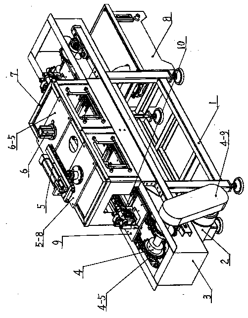
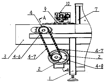
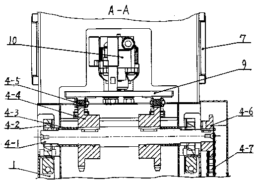
[0016] Examples, see attached Figure 1-8 Oil pump degreasing cleans up oil recovery tank 3 on the frame 1 of oil blowing equipment, oil collection tank 8 is housed on the frame 1 below the recovery oil tank 3 right ends, and is connected with pipeline between recovery oil tank 3 bottoms and oil collection tank 8. The top of the frame 1 is provided with a chain drive mechanism 4, and the front and rear sides above the left and right ends of the frame 1 are respectively fixed with a group of bearing seats 4-2, and the bearings of the corresponding bearing seats 4-2 at each end A main shaft 4-1 is worn respectively in the main shaft 4-1, and two transmission sprockets 4-4 are equipped with key connection respectively on the main shaft 4-1, pass between two transmission sprockets 4-4 on the same main shaft 4-1 through the main shaft 4-1. The axle shoulder limit of wheel 4-1. Use spacer sleeve one 4-3 spacing between two drive chain wheels 4-4 and the bearing in both sides bearin...
PUM
 Abstract
Description
Claims
Application Information
 - Generate Ideas
- Intellectual Property
- Life Sciences
- Materials
- Tech Scout
- Unparalleled Data Quality
- Higher Quality Content
- 60% Fewer Hallucinations
Browse by: Latest US Patents, China's latest patents, Technical Efficacy Thesaurus, Application Domain, Technology Topic, Popular Technical Reports.
© 2025 PatSnap. All rights reserved.Legal|Privacy policy|Modern Slavery Act Transparency Statement|Sitemap|About US| Contact US: help@patsnap.com