A single photon counting system with multi-parameter configuration
A single-photon counting and multi-parameter technology, applied in the field of photoelectric detection, can solve problems such as limiting the practicality of single-photon technology systems, increasing the overall dark count rate of the system, and increasing noise
- Summary
- Abstract
- Description
- Claims
- Application Information
AI Technical Summary
Problems solved by technology
Method used
Image

Examples
Embodiment 1
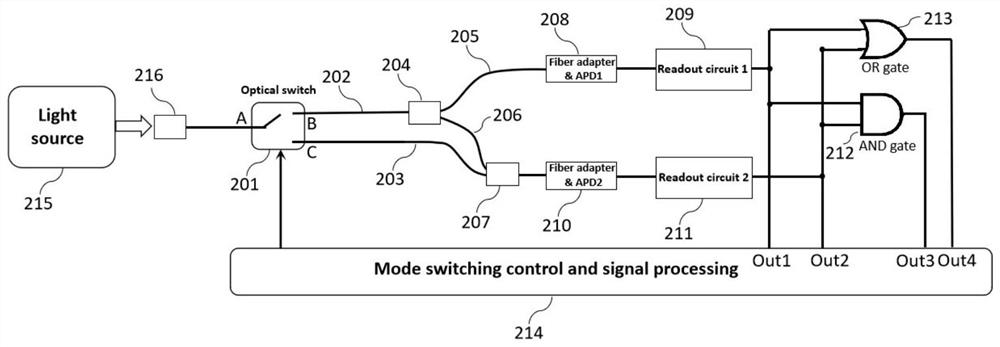
[0027] figure 2 An embodiment is given when the multi-parameter configurable single photon counting system is used for the measurement of optical signal intensity. The 1×2 electrically controlled optical switch 201, the first transmission fiber 202, the second transmission fiber 203, the fiber splitter 204, the third transmission fiber 205, the fourth transmission fiber 206, the fiber combiner 207, the first single photon Detector 208, first readout circuit 209, second single photon detector 210, second readout circuit 211, two-input logic AND gate 212, two-input logic OR gate 213, mode switching and signal processing module 214, light source 215 And fiber coupler 216. When the system is working, the optical signal sent by the light source enters the input end (A port) of the 1×2 electronically controlled optical switch through the fiber coupler, and the 1×2 electronically controlled optical switch guides the input optical signal to the output under external electronic contr...
Embodiment 2
[0034] Figure 5 An example in which a multi-parameter configurable single photon counting system is used for time-correlated single photon counting is given. 1×2 electrically controlled optical switch 301, the first transmission fiber 302, the second transmission fiber 303, the fiber splitter 304, the third transmission fiber 305, the fourth transmission fiber 306, the fiber combiner 307, the first single photon Detector 308, first readout circuit 309, second single photon detector 310, second readout circuit 311, two-input logic AND gate 312, two-input logic OR gate 313, mode switching and signal processing module 314, light source 315 , a fiber coupler 316, a time-to-digital converter 317, and a PC-side data processing system 318. When the system is working, the light source sends a pulse light signal through the fiber coupler and enters the input port (A port) of the 1×2 electronically controlled optical switch. At the same time, the light source sends a synchronous pulse...
PUM
 Abstract
Description
Claims
Application Information