Oral cavity cleaning drainage equipment

An oral cleaning and equipment technology, which is applied in the direction of cleaning teeth, suction equipment, body cavity massage equipment, etc., can solve the problems of safety hazards, pollution, cleaning fluid entering the trachea and esophagus, and achieve the effect of enhancing the sealing effect

Inactive Publication Date: 2020-03-24
THE AFFILIATED HOSPITAL OF QINGDAO UNIV
1 Cites 3 Cited by

AI-Extracted Technical Summary

Problems solved by technology

[0004] In order to make up for the deficiencies of the prior art, the oral irrigation and drainage device in the prior art is easy to pass the cleaning liquid into the trachea and esophagu...

Method used

As an embodiment of the present invention, the outside of the housing 1 is slidably connected with a brace 6; the brace 6 is provided with an arc-shaped groove 61 that matches the shape of the tooth arrangement; the brace 6 is inside A second cavity 62 is opened; the second cavity 62 is connected to the liquid inlet pipe 2 through a conduit; uniformly distributed spray ports 63 are opened in the arc-shaped groove 61; the liquid spray ports 63 are connected to the first The two cavities 62 are connected; the inner surface of the arc-shaped groove 61 is fixed with evenly distributed soft brushes; when working, when the device is put into the oral cavity, the upper and lower gums are occluded in the arc-shaped groove 61 After the liquid inlet pipe 2 is connected, the liquid enters the second cavity 62 along the conduit, and the cleaning liquid is sprayed on the surface of the gums and teeth through the liquid spray port 63 opened on the second cavity 62, and the gums and teet...

Abstract

The invention belongs to the technical field of stomatological medical instruments, and particularly relates to oral cavity cleaning drainage equipment which comprises a shell, a liquid inlet pipe, aninflation pipe and a flow guide pipe; one end of the shell is fixedly connected with an expansion head; the end, away from the shell, of the expansion head is fixedly connected with an expansion bag;the expansion bag is made of a soft silica gel material; a first cavity is formed in the expansion bag; an air outlet is formed in one side, far away from the shell, of the expansion bag in the firstcavity; adsorption holes are formed in the side surface of the expansion bag; the adsorption holes are communicated with a flow guide pipe through a guide pipe in the expansion bag; a first groove isformed in the end, close to the expansion head, of the shell; liquid spraying holes are evenly formed in the surface of the side, close to the first groove, of the liquid inlet pipe; a second grooveis formed in one side, far away from the expansion head, of the shell; the expansion bag is deformed and attached to the side wall of an oral cavity, the adsorption effect of the expansion bag and thecavity is enhanced through the adsorption holes, and therefore cleaning fluid is prevented from entering the trachea and the esophagus of a patient.

Application Domain

Cavity massageVibration massage +4

Technology Topic

Trach tubeStoma +6

Image

  • Oral cavity cleaning drainage equipment
  • Oral cavity cleaning drainage equipment
  • Oral cavity cleaning drainage equipment

Examples

  • Experimental program(1)

Example Embodiment

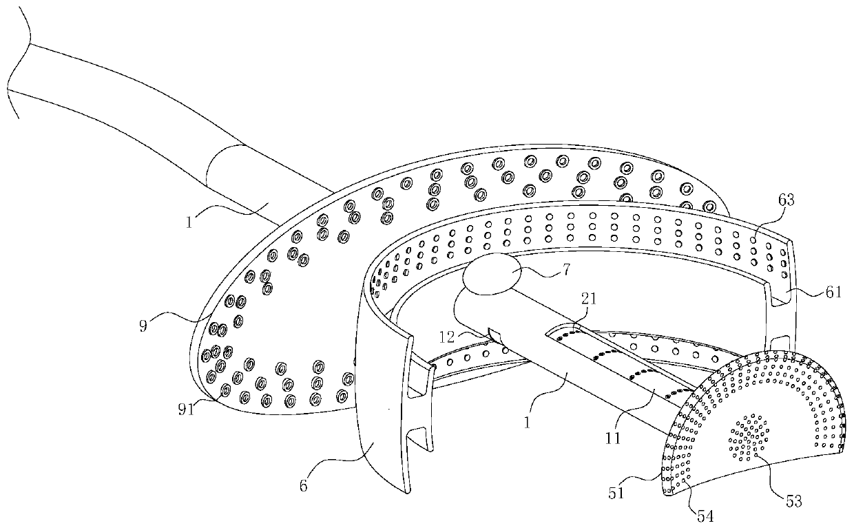
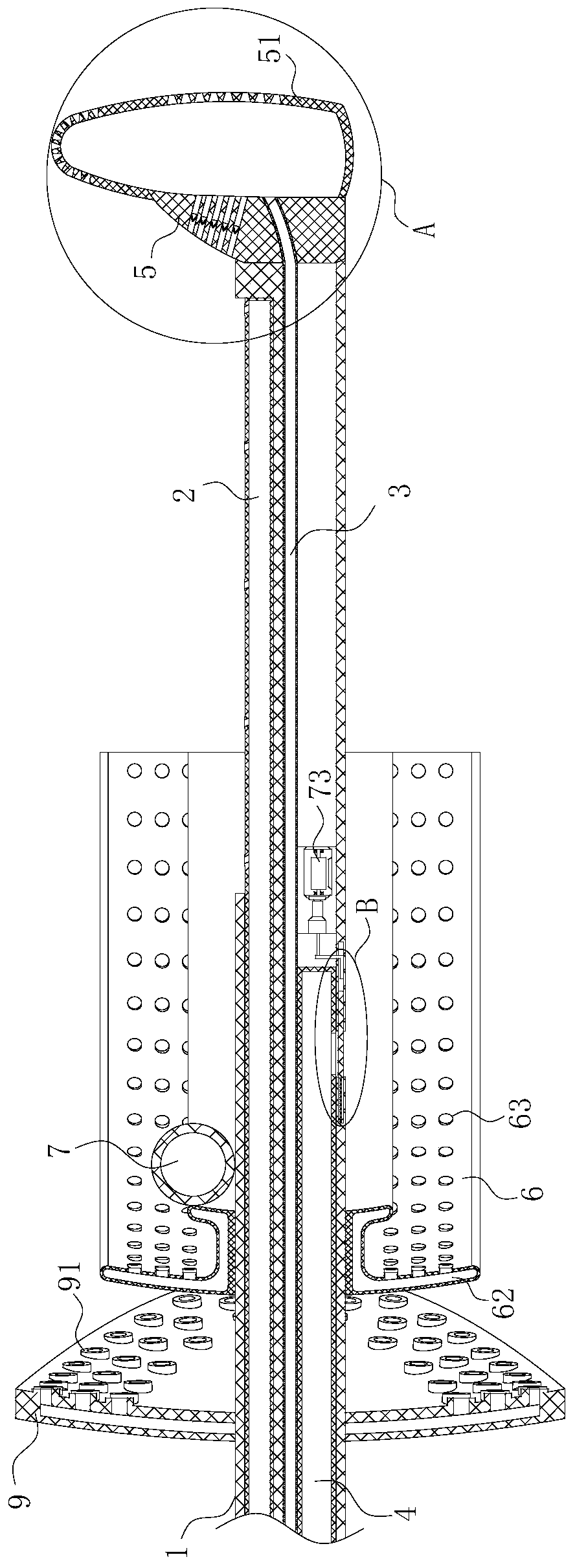
[0025] As an embodiment of the present invention, the outer side of the housing 1 is slidably connected with a mouthpiece 6; the mouthpiece 6 is provided with an arc-shaped groove 61 matching the shape of the tooth arrangement; the inside of the mouthpiece 6 is provided with a first Two cavities 62; The second cavity 62 communicates with the liquid inlet pipe 2 through a conduit; the arc-shaped groove 61 is provided with evenly distributed liquid spray ports 63; the liquid spray ports 63 are connected to the second cavity 62 conduction; the inner surface of the arc-shaped groove 61 is fixed with uniformly distributed soft brushes; when working, when the device is put into the oral cavity, the upper and lower gums are bitten in the arc-shaped groove 61, and the liquid After the tube 2 is turned on, the liquid enters the second cavity 62 along the catheter, and sprays the cleaning liquid on the gums and the surface of the teeth through the liquid spray port 63 opened in the second cavity 62 to clean the gums and the surface of the teeth. At the same time, the liquid spray port 63 drives the soft brush to scratch the surface of the teeth when spraying the cleaning liquid, which effectively increases the inside of the teeth that are easily overlooked during normal cleaning, and enhances the cleaning effect. At the same time, the presence of the braces 6 can also Sealing is formed by the contact between the lips and the outer wall of the braces 6, preventing the cleaning fluid from dripping on the outside of the oral cavity along the gap between the lips and the shell 1, causing pollution to the outside. At the same time, the cleaning fluid flows and sprays along the braces 6 to the inside of the oral cavity. The impact of the cleaning fluid sprayed from the liquid port 63 to the outside can also agitate the cleaning fluid flow in the oral cavity, so that the cleaning fluid oscillates in the oral cavity, and the cleaning of the oral cavity is performed more smoothly.
[0026] As an embodiment of the present invention, both the air outlet hole 53 and the suction hole 54 are tapered holes; the tapered tip of the air outlet hole 53 faces the outside of the first cavity 52, and the tapered tip of the suction hole 54 faces the expansion head 5. Inside; when working, the suction hole 54 has a tapered design, and the cone faces the inside of the expansion bag 51, which can effectively alleviate the suction effect of negative pressure on the side wall of the oral cavity, and avoid excessive negative pressure in the draft tube 4, and the suction hole 54 can absorb When it is on the side wall of the oral cavity, it will cause certain damage to the side wall of the oral cavity. At the same time, the tapered design of the adsorption hole 54 is designed inward, so that the adsorption hole 54 is located on the outer side of the expansion bag 51. The diameter is larger, which can better suck cleaning liquid and light secretion. The inflatable balloon 51 has a better sealing effect, and the tapered design of the air outlet 53 makes the gas flow out of the first cavity 52 more slowly, avoiding a large amount of gas outflow in the first cavity 52, causing the inflatable balloon 51 to shrink and expand the balloon. The adsorption effect between 51 and the side wall of the oral cavity is weakened; at the same time, the elastic material of the inflatable bladder 51 is matched with the air outlet 53, when the trachea exhales and inhales, the airflow impacts the inflatable bladder 51, causing the surface of the inflatable bladder 51 near the throat to deform When exhaling, the inflatable bladder 51 is squeezed in the opposite direction to the throat, so that the opening of the air outlet 53 is reduced, and the outflow of air in the first cavity 52 is reduced, thereby avoiding the inflatable bladder 51 and the inflatable head 5 during exhalation. Squeeze outward to increase the gap between the inflatable bladder 51 and the side wall of the oral cavity. When inhaling, negative pressure is formed in the throat to attract the inflatable bladder 51 toward the throat, so that the air outlet 53 can be opened more completely and the airflow can easily enter the throat. Perform breathing.
[0027] As an embodiment of the present invention, an airbag 7 is fixedly connected to the side of the mouthpiece 6 close to the expansion head 5; the side wall of the second groove 12 is provided with a first slide groove 71; in the first slide groove 71 A sliding plate 72 is slidably connected; the airbag 7 is connected to the first sliding groove 71 through a conduit; the housing 1 is located on the side of the first sliding groove 71 close to the expansion head 5, and a micro vibration motor 73 is installed; the micro vibration motor The 73 switch is connected to the sliding plate 72; when working, the cleaning fluid is sprayed to the inner wall of the oral cavity through the spray hole 21, and the cleaning fluid sprayed on the light side wall of the mouth cleans the surface of the oral cavity and gathers inside the oral cavity. When the liquid level continues to rise When the pressure in the mouth gradually increases, on the one hand, the increased pressure squeezes the inflatable bladder 51 toward the inside of the throat to enhance the anti-leakage effect, and on the other hand, the increased pressure matches the flow of cleaning fluid to squeeze the bladder 7. When the airbag 7 passes the internal air into the first chute 71 through the conduit, the sliding plate 72 in the first chute 71 moves to one end away from the airbag 7 under the squeezing of the airflow, thereby opening the closed second groove 12 , So that the cleaning liquid that is collected in the oral cavity and the impurities mixed in the cleaning liquid are guided to the outside of the oral cavity through the guide tube 4, when the sliding plate 72 opens the second groove 12, the suction of the guide tube 4 to the liquid flow makes The liquid flow quickly flows in the guide tube 4, and the negative pressure and the water pressure in the guide tube 4 cause the liquid flow to squeeze the sliding plate 72 when flowing through the second groove 12, so that the auxiliary sliding plate 72 continues to move away from the airbag 7 One end slides to squeeze the switch of the micro-vibration motor. The micro-vibration motor emits vibrations, which are transmitted to the cleaning liquid through the casing 1, causing the cleaning liquid to vibrate and enhance the cleaning effect. At the same time, the casing 1 is close to the tongue, which vibrates The shell 1 also massages the tongue, causing a slight displacement between the shell 1 and the tongue, which can effectively clean the tongue coating on the tongue surface, and at the same time, the cleaning liquid is continuously passed into the oral cavity and the liquid level rises to a certain level. The setting of discharge only at the height allows sufficient time for the cleaning solution to soak the inner wall of the cavity in the cleaning solution, so that the cleaning solution can completely dissolve the bacteria and impurities in the oral cavity, thereby completing the cleaning and disinfection of the oral cavity.
[0028] As an embodiment of the present invention, the expansion head 5 is provided with a second sliding groove 8 on one side surface close to the housing 1; the second sliding grooves 8 are all inclined to the upper wall of the oral cavity; the second sliding groove 8 is connected to the cavity of the expansion bag 51; the second chute 8 is fixedly connected with a one-way nozzle 81; when the trachea is in operation, the expansion bag 51 is deformed when the trachea is exhaling, so that the diameter of the outlet hole 53 is reduced , The gas in the first cavity 52 increases. The increase in the pressure in the first cavity 52 causes the one-way nozzle 81 to be squeezed through the second chute 8 and expanded, so that the gas is ejected out through the second chute 8. The second chute 8 enables the airflow to be ejected due to the inclined arrangement of the second chute 8 so that the airflow drives the liquid flow to impact, which can impact the liquid flow and produce a regular agitation effect on the cleaning liquid in the oral cavity. It can clean the adhering impurities on the side wall of the oral cavity more thoroughly. At the same time, the setting of the second chute 8 and the one-way nozzle 81 can also pressurize the inside of the oral cavity at the end of the cleaning work, and assist the cleaning fluid to be discharged from the oral cavity through the guide tube 4 In addition, a certain amount of drying treatment is performed on the oral cavity to make the patient's oral cavity more clean and dry after the cleaning work is completed.
[0029] As an embodiment of the present invention, a silicone pad 9 is fixedly connected to the side of the shell 1 close to the braces 6 away from the expansion head 5; the surface of the silicone pad 9 is provided with uniformly distributed negative pressure holes 91; the negative pressure The hole 91 is connected to the diversion tube 4 through a conduit; when working, the silicone pad 9 is attached to the outer wall of the lips before the cleaning work starts. After the diversion tube 4 is opened, the negative pressure in the diversion tube 4 passes through the negative pressure hole 91 to the outside of the lips. When it comes to adsorption, the silicone pad 9 is automatically attached to the outer wall of the lips, which can effectively prevent the oral cavity cleaning liquid from penetrating out when cleaning the oral cavity, and flowing out through the gaps in the lips, dripping on the patient’s clothing, the silicone pad 9 While the negative pressure holes 91 are in the least tight fit, the negative pressure holes 91 distributed at the opening and closing positions of the lips can also collect and drain the small amount of liquid that has leaked out, so that the liquid can be processed through the draft tube 4, The no-clean liquid entraps bacteria in the oral cavity and exposes them to the air, causing the bacteria to spread.
[0030] The specific workflow is as follows:
[0031] When working, put the cleaning and drainage device into the patient’s mouth with the flat side of the expansion head 5 facing the tongue until the expansion head 5 is close to the outside of the uvula. At this time, the device is turned on to control the inflation tube 3 to inflate into the first cavity 52. The gas in a cavity 52 gradually increases, causing the inflation balloon 51 to inflate. When the inflation balloon 51 touches the inner wall of the oral cavity, the suction hole 54 communicates with the diversion tube 4 through a catheter and the negative pressure in the diversion tube 4 causes the inflation balloon 51 to expand. 51 is adsorbed on the side wall of the mouth and the root of the tongue through the side suction hole 54 to form an obstacle to block the passage of the mouth and throat. At this time, the mouth is closed, the teeth are bitten in the braces 6, and the silicone pad 9 is attached to the lips Externally, the liquid inlet pipe 2 is conducted, so that the cleaning liquid in the liquid inlet pipe 2 is sprayed into the cavity and the arc-shaped groove 61 of the mouthpiece 6 through the liquid spray hole 21 and the liquid nozzle 63, and the cleaning liquid is on the liquid level in the oral cavity. As the airbag 7 is gradually raised, the airbag 7 is squeezed to make the sliding plate 72 slide, and then the guide tube 4 is opened to discharge the cleaning liquid, bacteria and impurities entrapped in the cleaning liquid, thereby completing the oral cavity cleaning.

PUM

no PUM

Description & Claims & Application Information

We can also present the details of the Description, Claims and Application information to help users get a comprehensive understanding of the technical details of the patent, such as background art, summary of invention, brief description of drawings, description of embodiments, and other original content. On the other hand, users can also determine the specific scope of protection of the technology through the list of claims; as well as understand the changes in the life cycle of the technology with the presentation of the patent timeline. Login to view more.

Similar technology patents

Automobile oil filter air tightness test automation device and test method thereof

InactiveCN110146236AGuaranteed blocking effectImprove the blocking effect
Owner:NANJING HANMINGZHI INTELLIGENT TECHNOLOGY CO LTD

Plugging agent capable of enhancing plugging performance of drilling fluid as well as plugging method and application thereof

PendingCN111690389AHigh sealing strengthImprove the blocking effect
Owner:BC P INC CHINA NAT PETROLEUM CORP +1

Coil-type equipment oil leakage plugging device and method

ActiveCN110822082AImprove the blocking effectimprove integrity
Owner:ELECTRIC POWER RESEARCH INSTITUTE OF STATE GRID SHANDONG ELECTRIC POWER COMPANY +3

Classification and recommendation of technical efficacy words

  • Improve the blocking effect

Automobile oil filter air tightness test automation device and test method thereof

InactiveCN110146236AGuaranteed blocking effectImprove the blocking effect
Owner:NANJING HANMINGZHI INTELLIGENT TECHNOLOGY CO LTD

Coil-type equipment oil leakage plugging device and method

ActiveCN110822082AImprove the blocking effectimprove integrity
Owner:ELECTRIC POWER RESEARCH INSTITUTE OF STATE GRID SHANDONG ELECTRIC POWER COMPANY +3

Plugging agent capable of enhancing plugging performance of drilling fluid as well as plugging method and application thereof

PendingCN111690389AHigh sealing strengthImprove the blocking effect
Owner:BC P INC CHINA NAT PETROLEUM CORP +1
Why Eureka
Try Eureka