Turbine disk cavity sealing structure with bypass bleed air

A turbine disk and bleed air technology, applied in the direction of leakage prevention, engine components, machines/engines, etc., can solve the problems of increasing the risk of airflow separation at the root of the rotor blade, the intensity of secondary flow loss, the reduction of turbine efficiency, and the increase of flow loss in turbine passages, etc. , to achieve the effects of good economy and realizability, reduced secondary flow loss, and improved turbine efficiency

Inactive Publication Date: 2020-03-24
AECC SICHUAN GAS TURBINE RES INST
View PDF0 Cites 13 Cited by
  • Summary
  • Abstract
  • Description
  • Claims
  • Application Information

AI Technical Summary

Problems solved by technology

[0004] The defects of the existing turbine disc cavity sealing structure are: figure 1 Among them, after the third cold air passes through the sealing structure composed of two sealed grate teeth and honeycomb, the total pressure loss of the cold air is relatively large, and the speed of the cold air and the pre-swirl angle of the cold air are both low, which is different from the mainstream gas at the root of the guide vane. There is a big difference, which leads to the radial and circumferential mixing of the sealed cold air with the high-speed fluid of the mainstream after entering the main channel, and causes the mainstream gas entering the root of the rotor blade to have a large negative angle of attack, resulting in Working at non-design point conditions will increase the risk of airflow separation at the root of the rotor and increase the intensity of the secondary flow loss in the channel, which will eventually increase the flow loss in the turbine channel, reduce turbine efficiency, and decrease performance

Method used


Image

  • Turbine disk cavity sealing structure with bypass bleed air
  • Turbine disk cavity sealing structure with bypass bleed air
  • Turbine disk cavity sealing structure with bypass bleed air

Examples


Embodiment Construction

[0037] In order to make the object, technical solution and advantages of the present invention clearer, the present invention will be described in further detail below in conjunction with specific embodiments and with reference to the accompanying drawings.

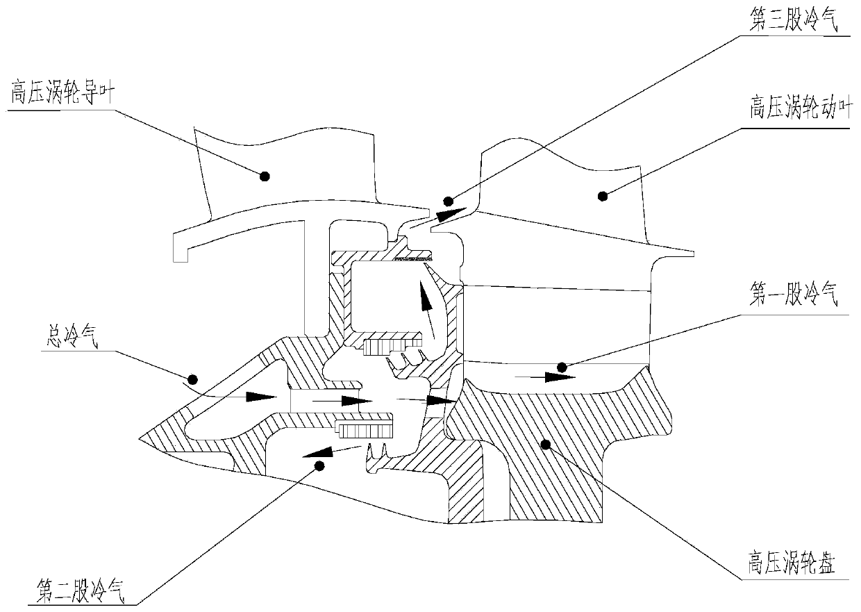
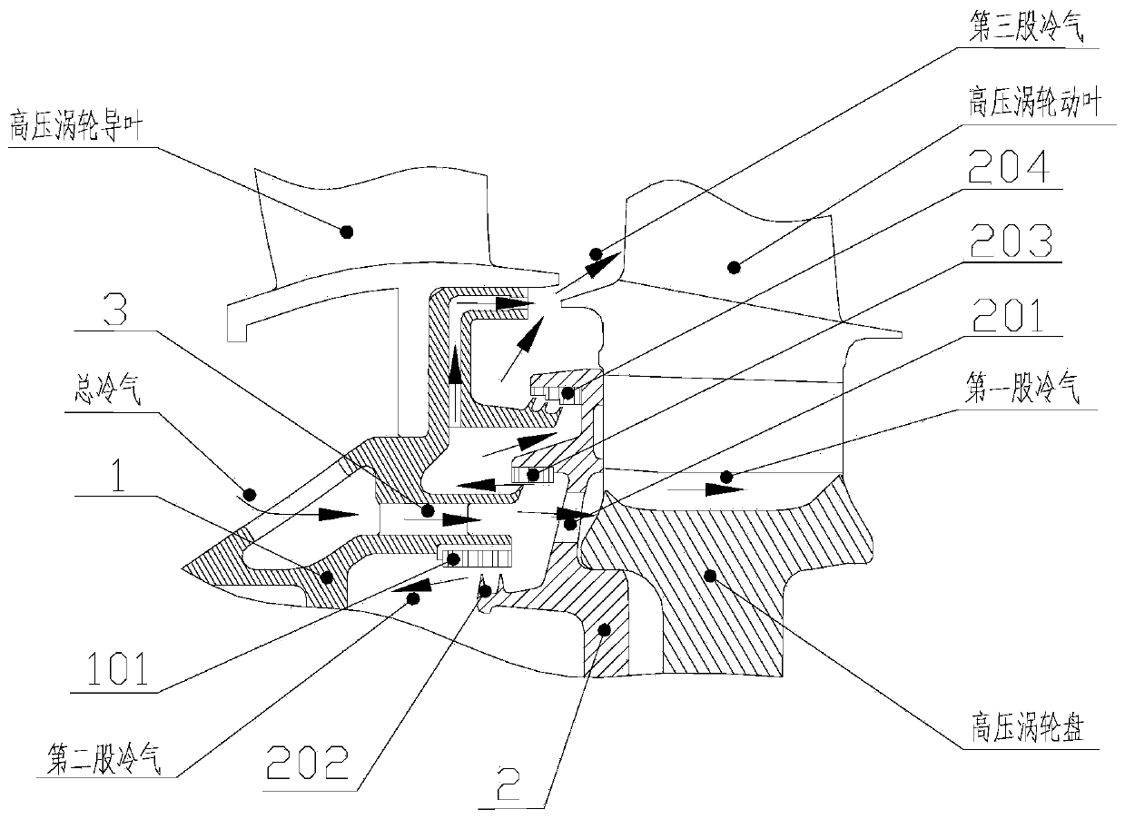
[0038] The sealing structure of the turbine disc cavity with bypass bleed air proposed by the present invention is as follows: figure 2 shown.

[0039] Including an inner support ring assembly 1 and a front baffle assembly 2, the inner support ring assembly 1 is provided with a pre-rotation nozzle 3.

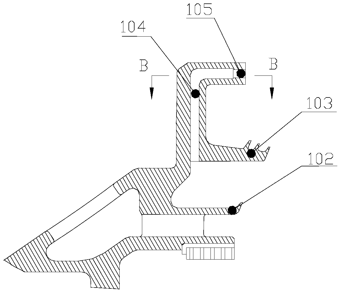
[0040] The inner support ring assembly 1 also includes a first honeycomb structure 101, a single grate structure 102, and a three-grate structure 103;

[0041] The front baffle assembly 2 includes a front baffle air inlet 201, two grate structures 202, a second honeycomb structure 203, and a third honeycomb structure 204;

[0042] The first honeycomb structure 101 and the two grate structures 202 form a sealing gap;

[...


PUM


Abstract

The invention relates to a turbine disk cavity sealing structure with bypass bleed air. The turbine disk cavity sealing structure with bypass bleed air comprises an inner support ring assembly and a front baffle assembly, wherein a bypass bleed air groove is formed in the inner support ring assembly, the bypass bleed air groove is a second flow path of a third path of cold air, and the cold air passing through the second flow path is mixed with the cold air of a first flow path at an inlet of a main flow path; the airflow speed and the pre-rotation angle of the sealed cold air outlet are increased, so that speed triangle difference with the main flow gas of a guide vane root outlet is reduced, the mixing of the sealed cold air and the main flow is reduced, the efficiency of the turbine isimproved, and a movable vane root is guaranteed to work in a design working condition.

Description

technical field [0001] The invention belongs to the field of gas turbine engines, and in particular relates to a turbine disk cavity sealing structure with bypass bleed air. Background technique [0002] The working principle of a gas turbine engine is to use the high-temperature and high-pressure gas generated by the mixed combustion of compressed air and fuel from the compressor to drive the turbine to rotate at high speed, and the turbine drives the compressor through the turbine shaft to form a continuous operation. A turbine consists of stationary vanes (which make up the stator part) and rotating blades (which make up the rotor part). In order to ensure the reliable operation of the turbine rotor and avoid friction between the rotor and stator, there is a certain gap between the rotor and stator turbine discs. The existence of axial and radial gaps between the guide vane and the root of the moving blade may cause high-temperature gas in the turbine channel to invade t...

Claims


Application Information

Patent Timeline
Patent Type & Authority Applications(China)
IPC IPC(8): F01D11/04F01D25/12
CPCF01D11/04F01D25/12
Inventor 张维涛贺进薛伟鹏杜鹏卿雄杰
Owner AECC SICHUAN GAS TURBINE RES INST
Why Eureka
Try Eureka