
Hydrogen circulation compression pump

A cyclic compression, hydrogen technology, applied in pumps, pump components, rotary piston pumps, etc., can solve problems such as unfavorable compression, loss of compression performance and service life of circulating compression pumps, and achieve the effect of improving quality and preventing leakage

Active Publication Date: 2020-03-24
博致新源(北京)科技有限公司
View PDF6 Cites 1 Cited by
  • Summary
  • Abstract
  • Description
  • Claims
  • Application Information

AI Technical Summary

Problems solved by technology

The existing commonly used hydrogen cycle compression pump adopts a claw structure, and the hydrogen gas coming out of the fuel cell stack contains moisture, which is not conducive to its compression, and damages the compression performance and service life of the cycle compression pump. In addition, the moving parts used Impurities such as lubricating oil are easily brought into hydrogen

Method used


Image

  • Hydrogen circulation compression pump

Examples


Embodiment Construction

[0017] A hydrogen circulating compression pump provided by the present invention will be further described in detail and completely below in conjunction with the embodiments. The embodiments described below are exemplary only for explaining the present invention and should not be construed as limiting the present invention.

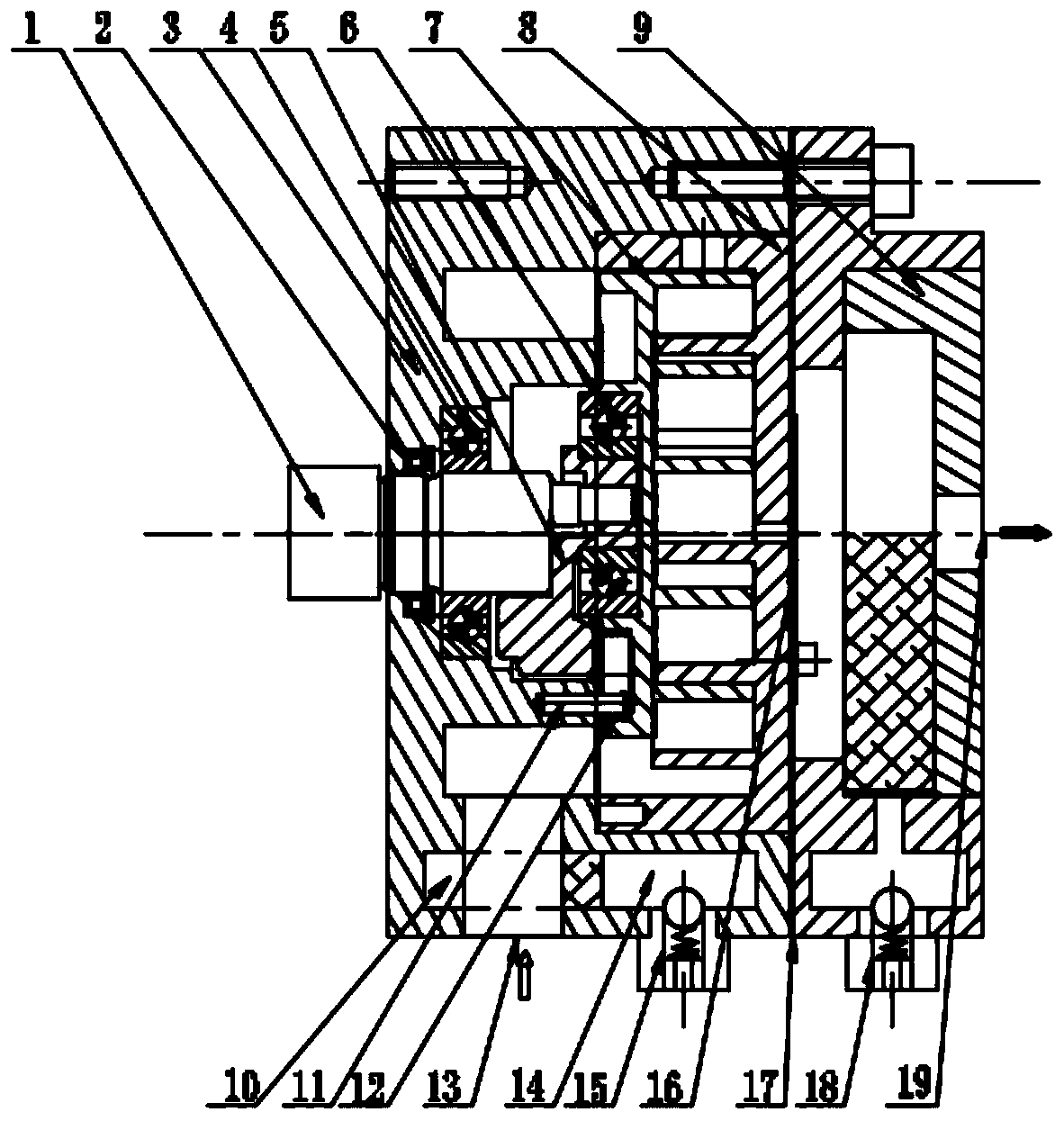
[0018] A hydrogen circulation compressor pump, such as figure 1 As shown, it includes a housing 3 and a drive shaft 1 installed on the housing 3, a movable scroll 7 and a fixed scroll 8, the drive shaft 1 is connected and drives the movable scroll 7 to rotate relative to the fixed scroll 8, A working chamber whose volume gradually changes is formed. Both the movable scroll 7 and the fixed scroll 8 are scroll-shaped, specifically, the movable scroll 7 is an involute moving scroll that eccentrically revolves and translates, and the fixed scroll 8 is a fixed involute scroll. The open scroll, the orbiting scroll 7 and the fixed scroll 8 cooperate to form a ...


PUM


Abstract

The invention discloses a hydrogen circulation compression pump. The hydrogen circulation compression pump comprises a shell body, a driving shaft, a moving scroll plate and a static scroll plate, wherein the driving shaft, the moving scroll plate and the static scroll plate are installed on the shell body, the driving scroll plate is driven by the driving shaft to rotate relative to the static scroll plate, a working cavity with a gradually changing volume is formed, an opened accommodation cavity is formed in the shell body, the moving scroll plate and the static scroll plate are located inthe accommodation cavity, the driving shaft penetrates through the shell body, and then is connected with the moving scroll plate, a main bearing is arranged between the driving shaft and the shell body, a moving plate bearing is arranged between the driving shaft and the moving scroll plate, the main bearing and the moving plate bearing are both ceramic bearings without lubrication, a hydrogen inlet, a hydrogen exhaust port and a water removing device are further arranged on the shell body, the hydrogen inlet, the working cavity and the hydrogen exhaust port sequentially communicate with oneanother, the water removing device comprises two water absorbing layers, the first water absorbing layer is located between the hydrogen inlet and the working cavity, and the second water absorbing layer is located between the hydrogen exhaust port and the working cavity. According to the hydrogen circulation compression pump, the situations that impurities such as lubricating oil enter the working cavity and hydrogen is leaked are mainly avoided; and the water removing device is arranged, and the quality of the hydrogen is improved.

Description

technical field [0001] The invention belongs to the technical field of hydrogen fuel cells, in particular to a hydrogen circulation compression pump. Background technique [0002] New energy vehicles are the development trend of the automotive industry due to their energy-saving and environmental protection features. Hydrogen fuel cells have gradually become one of the important driving forces for new energy vehicles due to their advantages of no pollution, no noise, and high efficiency. The hydrogen circulation compressor pump is an indispensable and important component for continuously circulating hydrogen into the hydrogen fuel cell reactor. The existing commonly used hydrogen cycle compression pump adopts a claw structure, and the hydrogen gas coming out of the fuel cell stack contains moisture, which is not conducive to its compression, and damages the compression performance and service life of the cycle compression pump. In addition, the moving parts used Impurities ...

Claims


Application Information

Patent Timeline
Patent Type & Authority Applications(China)
IPC IPC(8): F04C18/02F04C29/00F04C27/00
CPCF04C18/0215F04C29/00F04C29/0092F04C29/0021F04C27/00F04C2240/50
Inventor 黄政西袁涛黄伟贤
Owner 博致新源(北京)科技有限公司
Learn More