
Broadband vibration energy harvester

An energy harvester and wide-band technology, applied in the field of energy harvesting, can solve the problems of large output current, only tens to hundreds of millivolts, the best load is usually tens to hundreds of ohms, and small output current.

Active Publication Date: 2020-03-24
BEIJING MECHANICAL EQUIP INST
View PDF4 Cites 4 Cited by
  • Summary
  • Abstract
  • Description
  • Claims
  • Application Information

AI Technical Summary

Problems solved by technology

The three types of energy harvesters have their own different characteristics. The output voltage of the piezoelectric energy harvester is relatively large, but the large internal resistance results in a small output current, usually only a few microamperes to tens of microamperes. The best load generally reaches tens of kΩ to 1MΩ; the output current of the electromagnetic energy harvester is relatively large, but the output voltage is only tens to hundreds of millivolts, and the best load is usually tens to hundreds of ohms; the electrostatic energy harvester Electret or turn-on voltage is required to work normally, and there is also the problem of small output current
Therefore, the vibration energy harvester needs to solve the problem of small output power in the low frequency working environment

Method used


Image

  • Broadband vibration energy harvester
  • Broadband vibration energy harvester
  • Broadband vibration energy harvester

Examples


Embodiment Construction

[0023] Example embodiments will now be described more fully with reference to the accompanying drawings. Example embodiments may, however, be embodied in many forms and should not be construed as limited to the examples set forth herein; rather, these embodiments are provided so that this disclosure will be thorough and complete and will fully convey the concept of example embodiments to those skilled in the art. The drawings are merely schematic illustrations of the present disclosure and are not necessarily drawn to scale. The same reference numerals in the drawings denote the same or similar parts, and thus repeated descriptions thereof will be omitted.

[0024] Furthermore, the described features, structures, or characteristics may be combined in any suitable manner in one or more embodiments. In the following description, numerous specific details are provided in order to give a thorough understanding of embodiments of the present disclosure. However, those skilled in ...


PUM


Abstract

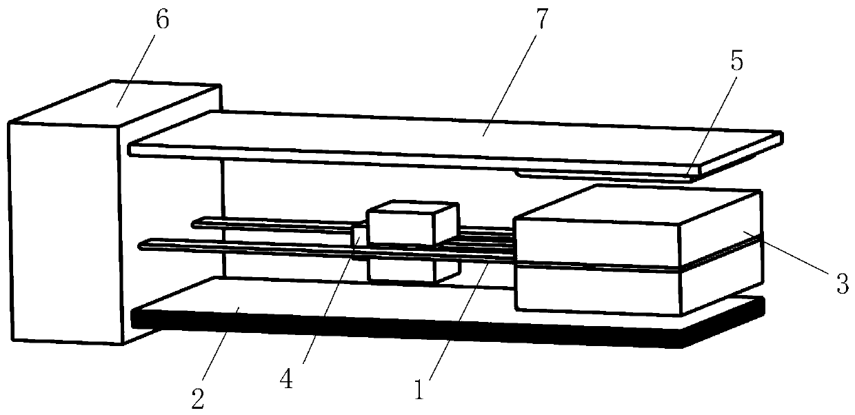
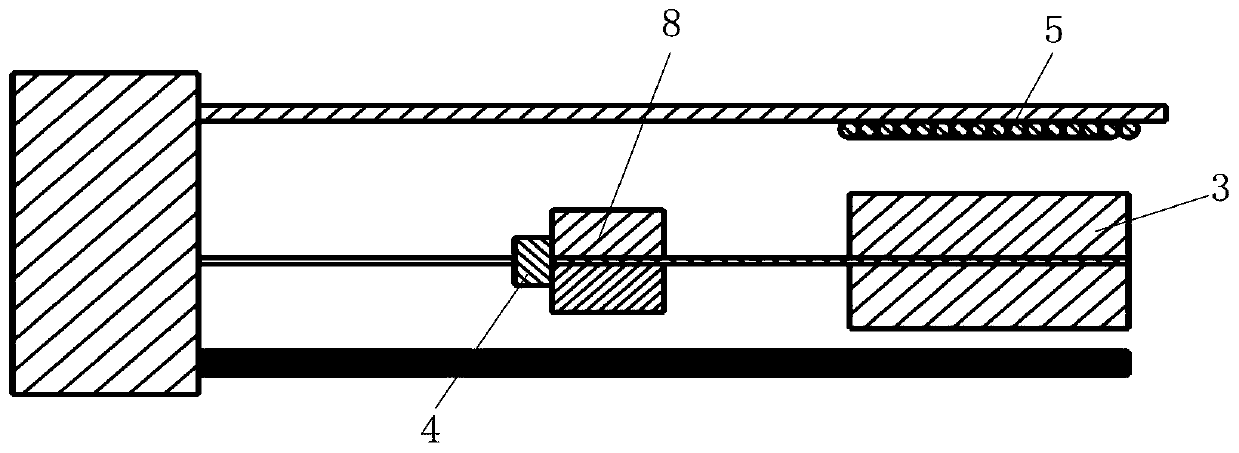
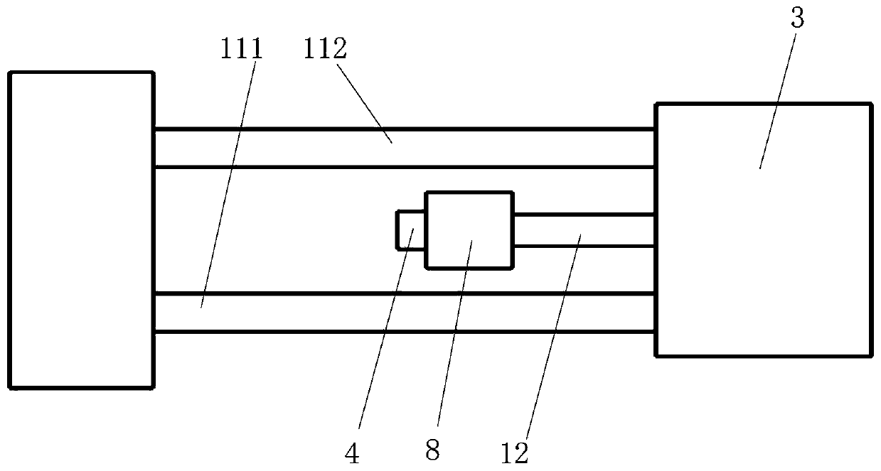
The invention discloses a broadband vibration energy harvester. The device comprises a low-frequency vibration structure, a high-frequency piezoelectric composite beam, a first moving magnet, a secondmoving magnet and a coil, the low-frequency vibration structure comprises a first vibration beam and a second vibration beam. One end of the first vibrating beam is fixed; the free end of the first vibrating beam and one end of the second vibrating beam are fixedly connected with the first moving magnet respectively; the free end of the second vibration beam is fixedly connected with the second movable magnet; the coil and the high-frequency piezoelectric composite beam are located on the two sides of the vibration direction of the low-frequency vibration structure, and the low-frequency vibration structure drives the first movable magnet and the second movable magnet to vibrate under vibration excitation so as to output electric energy according to electromagnetic induction between the first movable magnet and the coil and the piezoelectric effect of the second movable magnet touching the high-frequency piezoelectric composite beam. The broadband vibration energy harvester provided by the invention has a low-frequency broadband energy harvesting effect, and can output relatively high voltage and relatively high current and a wider optimal load application range at the same time.

Description

technical field [0001] The invention belongs to the technical field of energy harvesting, in particular to a vibration energy harvester. Background technique [0002] With the development of microsystem technology, the application fields and scope of various microdevices are becoming more and more extensive, especially in the application environment of airtight, rotating and relatively limited space size, due to the limitation of system size and the limited Due to the poor adaptability of the line energy supply environment and other problems, the traditional energy supply method cannot meet the new energy supply requirements integrated with micro-devices. Therefore, energy harvesting technology that can work for a long time, occupy a small working space, and has strong environmental adaptability has become a research hotspot in the field of micro-energy in recent years. [0003] Energy harvesting technology realizes the conversion of vibration energy, thermal energy, and el...

Claims


Application Information

Patent Timeline
Patent Type & Authority Applications(China)
IPC IPC(8): H02N2/18H02K35/02
CPCH02K35/02H02N2/188
Inventor 李平许诺王忠晶张斌安灵椿
Owner BEIJING MECHANICAL EQUIP INST
Learn More