Flue with purification function and iron and steel smelting equipment

A flue and functional technology, applied in the direction of chemical instruments and methods, dispersed particle filtration, membrane filter, etc., can solve the problems of pollution, general convenience, etc., and achieve the effect of improving purification speed, good stability, and good sealing

Inactive Publication Date: 2020-03-27
熊雪根
View PDF5 Cites 0 Cited by
  • Summary
  • Abstract
  • Description
  • Claims
  • Application Information

AI Technical Summary

Problems solved by technology

[0003] At present, a large amount of exhaust gas will be generated in the process of iron and steel smelting. If these exhaust gases are directly discharged to the outside, it will easily cause pollution. The current equipment for purification of iron and steel smelting exhaust gas is generally convenient.

Method used


Image

  • Flue with purification function and iron and steel smelting equipment
  • Flue with purification function and iron and steel smelting equipment
  • Flue with purification function and iron and steel smelting equipment

Examples


Embodiment 1

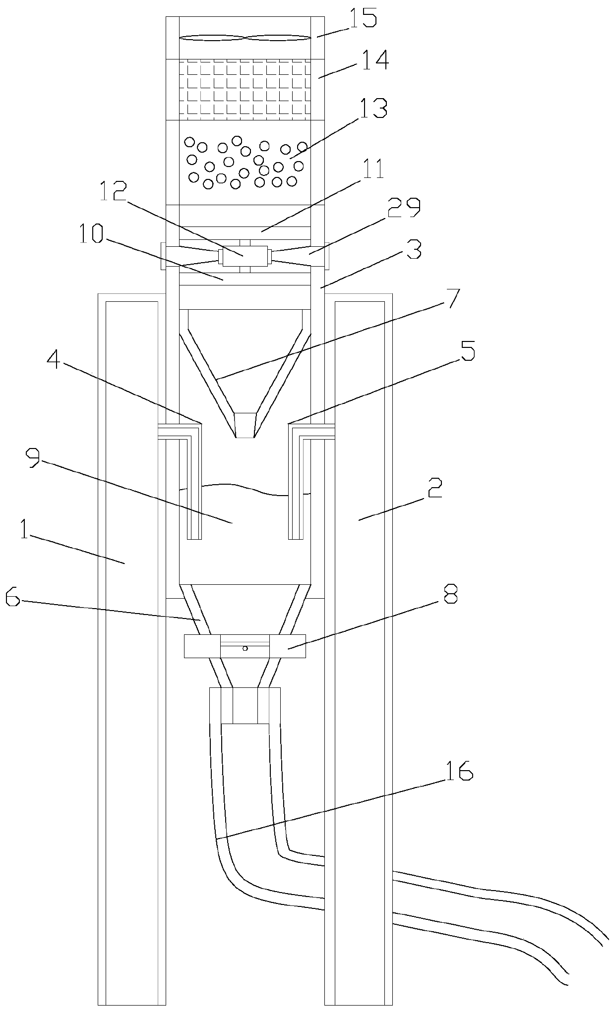
[0028] Such as figure 1As shown, a flue with purification function includes a first smoke inlet pipe 1, a second smoke inlet pipe 2 and an exhaust pipe 3, and the tops of the first smoke inlet pipe 1 and the second smoke inlet pipe 2 are both Sealing arrangement, the first smoke inlet pipe 1 and the second smoke inlet pipe 2 are fixedly connected with the exhaust pipe 3, and the first air inlet pipe 4, the second air inlet pipe 5, the first Funnel 6 and second funnel 7, described first funnel 6 is provided with butterfly valve 8, is formed with storage chamber 9 between described first funnel 6 and second funnel 7, is provided with reaction liquid ( not shown), one end of the first air inlet pipe 4 and the second air inlet pipe 5 is inserted into the reaction liquid, and the other end of the first air inlet pipe 4 and the second air inlet pipe 5 runs through the first smoke inlet pipe 1 and the second air inlet pipe respectively. The smoke pipe 2, the first smoke inlet pipe 1...

Embodiment 2

[0031] like Figure 1-5 As shown, a flue with purification function includes a first smoke inlet pipe 1, a second smoke inlet pipe 2 and an exhaust pipe 3, and the tops of the first smoke inlet pipe 1 and the second smoke inlet pipe 2 are both Sealing arrangement, the first smoke inlet pipe 1 and the second smoke inlet pipe 2 are fixedly connected with the exhaust pipe 3, and the first air inlet pipe 4, the second air inlet pipe 5, the first Funnel 6 and second funnel 7, described first funnel 6 is provided with butterfly valve 8, is formed with storage chamber 9 between described first funnel 6 and second funnel 7, is provided with reaction liquid ( not shown), one end of the first air inlet pipe 4 and the second air inlet pipe 5 is inserted into the reaction liquid, and the other end of the first air inlet pipe 4 and the second air inlet pipe 5 runs through the first smoke inlet pipe 1 and the second air inlet pipe respectively. The smoke pipe 2, the first smoke inlet pipe ...


PUM


Abstract

The invention discloses a flue with a purification function and steel smelting equipment. The flue comprises a first smoke inlet pipe, a second smoke inlet pipe and an air exhaust pipe. A first air inlet pipe, a second air inlet pipe, a first funnel and a second funnel are arranged in the air exhaust pipe. A butterfly valve is arranged on the first funnel, a storage cavity is formed between the first funnel and the second funnel, reaction liquid is arranged in the storage cavity, reaction liquid is inserted into one end of the first gas inlet pipe and one end of the second gas inlet pipe, a rotational flow plate and an air exhaust rotary vane are arranged above the second funnel, a double-shaft motor is arranged between the rotational flow plate and the air exhaust rotary vane, a tail endof the air exhaust pipe is sequentially connected with a first filtering device, a second filtering device and an air exhaust device, and the first filtering device, the second filtering device and the air exhaust device are all detachably connected with the air exhaust pipe. The flue with a purification function has good use convenience.

Description

technical field [0001] The invention relates to a flue and iron and steel smelting equipment with purification function. Background technique [0002] Most modern ironmaking uses blast furnace ironmaking, and some use direct reduction ironmaking method and electric furnace ironmaking method. Steelmaking mainly uses pig iron smelted in blast furnaces, sponge iron smelted by direct reduction ironmaking, and scrap steel as raw materials, which are smelted into steel by different methods. The basic production process is to smelt iron ore into pig iron in an iron-smelting furnace, then use pig iron as raw material to smelt steel by different methods, and then cast it into ingots or continuous casting slabs. [0003] At present, a large amount of exhaust gas will be generated in the process of iron and steel smelting. If these exhaust gases are directly discharged to the outside, it will easily cause pollution. The current equipment for purification of iron and steel smelting exh...

Claims


Application Information

Patent Timeline
Patent Type & Authority Applications(China)
IPC IPC(8): B01D53/78B01D46/00B01D46/42
CPCB01D53/78B01D46/0045B01D46/42B01D2258/025B01D2267/60B01D2267/40B01D46/62
Inventor 不公告发明人
Owner 熊雪根
Why Eureka
Try Eureka