
Combustion chamber with spiral-flow type flame tube

A flame cylinder and combustion chamber technology, applied in the field of aero-engine combustion chambers, can solve problems such as structural impact and pollutant emission restrictions, and achieve the effects of reducing emissions, improving combustion efficiency, and high feasibility

Inactive Publication Date: 2020-03-27
NORTHWESTERN POLYTECHNICAL UNIV
View PDF8 Cites 6 Cited by
  • Summary
  • Abstract
  • Description
  • Claims
  • Application Information

AI Technical Summary

Problems solved by technology

At present, there are low-pollution combustors that use lean oil premixed pre-evaporation technology to control flame temperature to reduce the formation of nitrogen oxides, and staged combustion technology to reduce pollutant emissions, but these two methods may lead to Auto-ignition or flashback occurs at high temperature, and the combustion chamber is risky to operate near the lean flameout limit. Therefore, the operation of the two is greatly affected by the structure of the combustion chamber itself, and the reduction of pollutant emissions is also limited.

Method used


Image

  • Combustion chamber with spiral-flow type flame tube
  • Combustion chamber with spiral-flow type flame tube
  • Combustion chamber with spiral-flow type flame tube

Examples


Embodiment Construction

[0022] The present invention will now be further described in conjunction with the drawings:

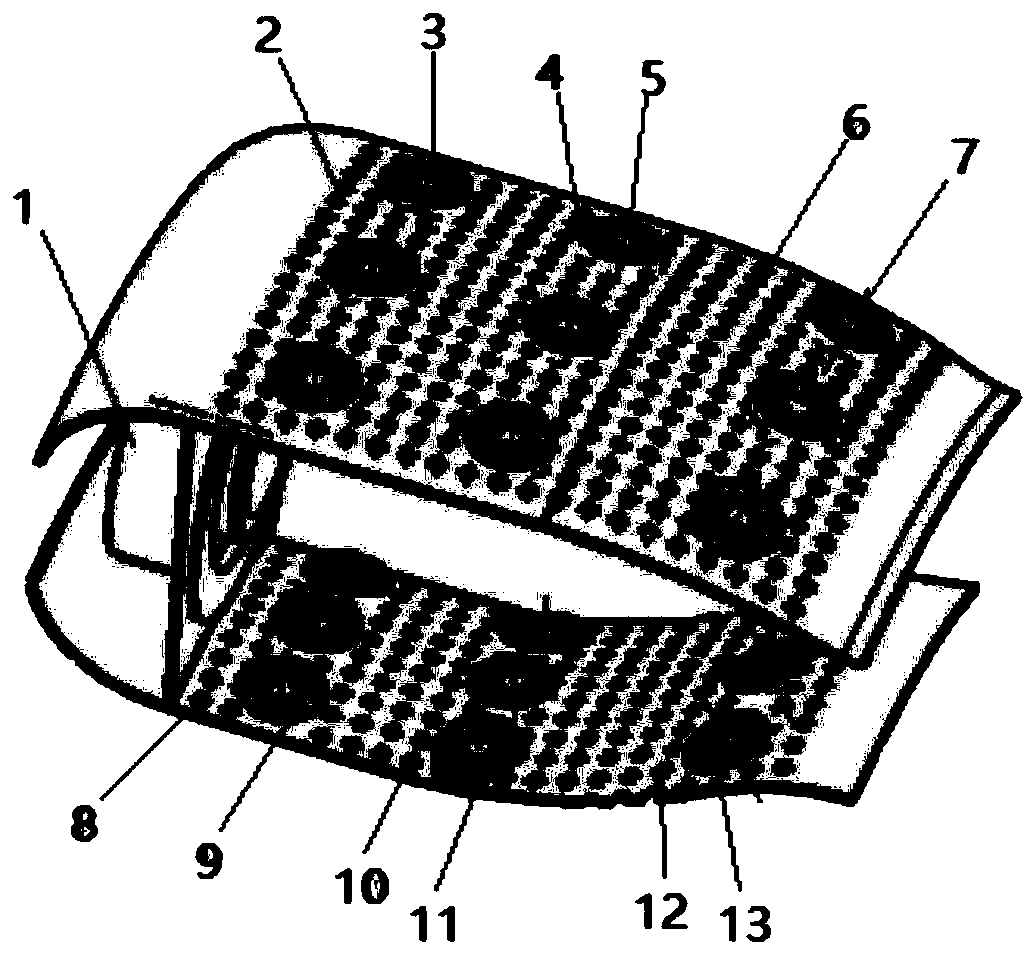
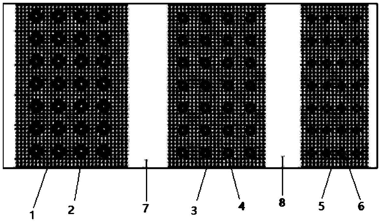
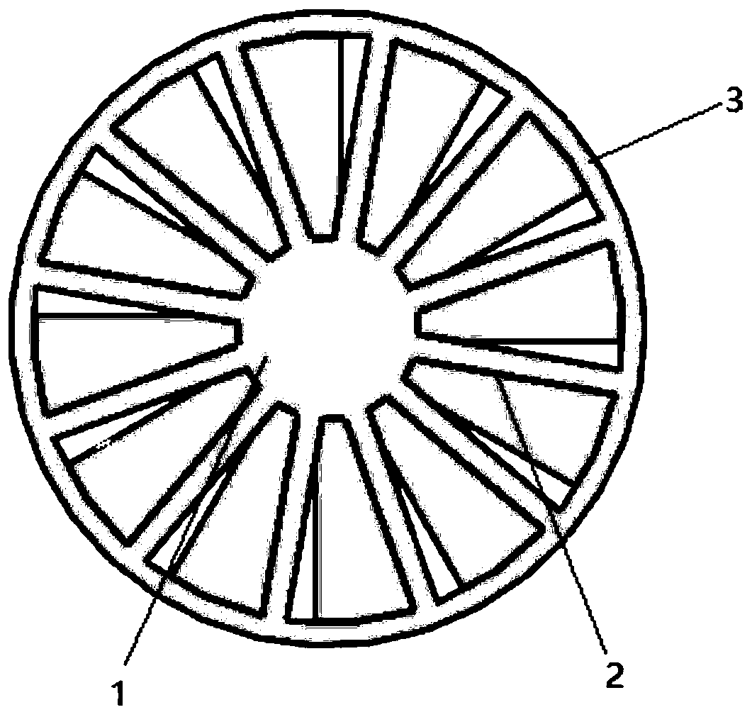
[0023] Combine figure 1 , figure 2 , image 3 , The present invention is a combustion chamber with a swirling flame tube. figure 1 Is a schematic diagram of a combustion chamber with a swirling flame tube, figure 2 An expanded view of the combustion chamber wall with a swirling flame tube, image 3 Schematic diagram of the swirl hole.

[0024] In order to fully heat and burn the fuel in the flame tube of the combustion chamber, swirl holes are added on the wall of the flame tube to form a new type of swirl flame tube. The fuel is sprayed out through the central nozzle and is fully mixed with the rotating air entering the front swirler 1 to form the return zone of the main combustion zone. However, the flame spray range in the recirculation zone is small, and the combustion range cannot reach all areas in the main combustion zone. Therefore, the problem of incomplete combustion is inev...


PUM


Abstract

The invention provides a combustion chamber with a spiral-flow type flame tube, and relates to the field of aero-engine combustion chambers. On the basis of different effects of a main combustion hole, a middle hole and a mixing hole of an original combustion chamber flame tube, spiral-flow type airflow holes are additionally formed in three different parts of the wall surface of the flame tube. Rotational flow gas entering the main combustion area is mixed with mixed fuel gas jetted near a swirler, and the area of a backflow area is increased. Then, the gas flow which is fully combusted in the main combustion area flows into the middle area and is further fully combusted with rotational flow entering from the middle hole, so that uncombusted gas and middle combustion products can be effectively and completely combusted. Finally, generated incomplete combustion products and residual fuel oil pass through the mixing area, lean oil combustion is conducted on the incomplete combustion products and the residual fuel oil and rotational flow gas entering the mixing hole through the tail portion of flame sprayed out of the main combustion area, and extremely-low emission of pollutants isachieved. The combustion chamber can be applied to low-pollution aero-engines.

Description

Technical field [0001] The invention belongs to the field of aeroengine combustion chambers, and particularly relates to a combustion chamber with a swirling flame tube. Background technique [0002] With the rapid development of human civilization, the international aviation industry has also grown stronger. This has brought great convenience to global economic development and communication, but it also caused many environmental problems. According to valid data, in 1999, aviation industry’s emissions of greenhouse gases into the atmosphere accounted for 3.5% of all human activities. This means that the development of the aviation industry has also seriously affected the atmospheric environment. Therefore, the emission requirements for aviation engines are also taller and taller. Investigations have shown that the emission requirements for nitrogen oxides (NOx) of aero engines are 45% to 60% lower than the emission standards set by the International Civil Aviation Organization....

Claims


Application Information

Patent Timeline
IPC IPC(8): F23R3/56F23R3/38F23R3/28
CPCF23R3/286F23R3/38F23R3/56
Inventor 张群李小龙程祥旺胡凡
Owner NORTHWESTERN POLYTECHNICAL UNIV
Learn More