Control method, device, equipment and storage medium of air source heat pump unit

A technology of air source heat pump and control method, applied in the direction of space heating and ventilation control input, mechanical equipment, lighting and heating equipment, etc., which can solve the problems of insufficient heat supply, failure to reach users, and different heat preservation effects, etc. To achieve the effect of reducing energy loss

Active Publication Date: 2021-02-12
GREE ELECTRIC APPLIANCES INC
View PDF6 Cites 0 Cited by
  • Summary
  • Abstract
  • Description
  • Claims
  • Application Information

AI Technical Summary

Problems solved by technology

[0003] However, the current buildings installed with air source heat pump units cause different building materials and different insulation effects. If the water temperature is used as the control target, for buildings with poor insulation effects, the temperature inside the building may not meet the needs of users. For buildings with good thermal insulation effect, when the water temperature reaches the desired temperature, the building may be overheated. Therefore, if the current unit takes the water temperature as the control target, it may lead to insufficient or excess heat supply, resulting in the consumption of the unit. high battery

Method used


Image

  • Control method, device, equipment and storage medium of air source heat pump unit
  • Control method, device, equipment and storage medium of air source heat pump unit
  • Control method, device, equipment and storage medium of air source heat pump unit

Examples


Embodiment 1

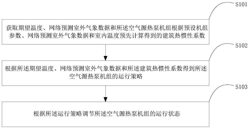
[0055] see figure 1 , figure 1 It is a schematic flowchart of a control method for an air source heat pump unit provided in Embodiment 1 of the present application.

[0056] Such as figure 1As shown, the control method of the air source heat pump unit provided in this embodiment may include:

[0057] Step S101, obtaining expected temperature, network-predicted outdoor weather data, and building thermal inertia coefficient pre-calculated by the air source heat pump unit according to preset unit parameters, network-predicted outdoor weather data and indoor temperature.

[0058] It should be noted that the expected temperature is the temperature value expected to maintain the temperature in the building, and the network-predicted outdoor weather data is the predicted data obtained from the Internet, which may include outdoor ambient temperature, outdoor ambient humidity, solar radiation, and the like.

[0059] In addition, the thermal inertia coefficient of a building can refl...

Embodiment 2

[0086] see Figure 5 , Figure 5 It is a schematic structural diagram of a control device for an air source heat pump unit provided in Embodiment 2 of the present application.

[0087] Such as Figure 5 As shown, the control device of the air source heat pump unit provided in this embodiment may include:

[0088] The first acquisition module 51 is used to acquire the desired temperature, the network-predicted outdoor weather data and the building thermal inertia coefficient pre-calculated by the air source heat pump unit according to the preset unit parameters, the network-predicted outdoor weather data and the indoor temperature;

[0089] The processing module 52 is used to obtain the operation strategy of the air source heat pump unit according to the expected temperature, network predicted outdoor weather data and the building thermal inertia coefficient;

[0090] An adjustment module 53, configured to adjust the operating state of the air source heat pump unit according...

Embodiment 3

[0105] see Image 6 , Image 6 It is a schematic structural diagram of a control device for an air source heat pump unit provided in Embodiment 3 of the present application.

[0106] Such as Image 6 As shown, the control equipment of the air source heat pump unit provided in this embodiment may include:

[0107] a processor 61, and a memory 62 connected to the processor;

[0108] The memory is used to store a computer program, and the computer program is at least used to execute the following control method of the air source heat pump unit:

[0109] Acquiring expected temperature, network forecasted outdoor weather data and building thermal inertia coefficient pre-calculated by said air source heat pump unit according to preset unit parameters, network forecasted outdoor weather data and indoor temperature;

[0110] Obtaining the operation strategy of the air source heat pump unit according to the expected temperature, network predicted outdoor meteorological data and the...


PUM


Abstract

The invention relates to a control method, device and equipment of an air source heat pump unit and a storage medium. The method comprises the steps that expected temperature, network predicted outdoor meteorological data and a building thermal inertia coefficient calculated in advance by the air source heat pump unit according to preset unit parameters, network predicted outdoor meteorological data and indoor temperature are obtained; according to the expected temperature, the network predicted outdoor meteorological data and the building thermal inertia coefficient, an operation strategy ofthe air source heat pump unit is obtained; and the operation state of the air source heat pump unit is adjusted according to the operation strategy. Therefore, the operation strategy obtained according to the expected temperature, the network predicted outdoor meteorological data and the building thermal inertia coefficient considers the building thermal inertia coefficient, namely the heat preservation effect of the building, and the optimal operation strategy can be given according to different heat preservation effects of different buildings when the unit is controlled to operate, so that the energy loss is effectively reduced.

Description

technical field [0001] The present application relates to the technical field of air conditioning, and in particular to a control method, device, equipment and storage medium of an air source heat pump unit. Background technique [0002] With the popularity of air source heat pump units, the level of energy consumption of the unit has attracted more and more attention from users. At present, the water temperature is generally used as the control target for air source heat pump units during operation. When the water temperature reaches the expected value, the heating is stopped. When the water temperature Reheat when below desired temperature. [0003] However, the current buildings installed with air source heat pump units cause different building materials and different insulation effects. If the water temperature is used as the control target, for buildings with poor insulation effects, the temperature inside the building may not meet the needs of users. For buildings wit...

Claims


Application Information

Patent Timeline
Patent Type & Authority Patents(China)
IPC IPC(8): F24F11/30F24F11/64F24F11/83F24F11/86F24F11/88F24D3/18F24F110/12F24F130/10
CPCF24D3/18F24F11/30F24F11/64F24F11/83F24F11/86F24F11/88F24F2110/12F24F2130/10
Inventor 李天阳陈晨林海佳尚瑞
Owner GREE ELECTRIC APPLIANCES INC
Why Eureka
Try Eureka