Supercharge Your Innovation With Domain-Expert AI Agents!

Built-in permanent magnet motor rotor structure

A permanent magnet motor, rotor structure technology, applied in the magnetic circuit shape/style/structure, magnetic circuit rotating parts, magnetic circuit and other directions, can solve the problems of reducing the power factor of the motor, increasing the iron loss of the motor, reducing the power factor, etc. Achieve the effect of reducing torque ripple, reducing stator iron loss, and reducing motor noise

Pending Publication Date: 2020-03-27
CHANGZHOU HONGHUI POWER TECH
View PDF1 Cites 0 Cited by
  • Summary
  • Abstract
  • Description
  • Claims
  • Application Information

AI Technical Summary

Problems solved by technology

[0002] The mainstream structure of the current magnetism-concentrating permanent magnet motor rotor is as follows: figure 1 As shown, the permanent magnets are radially embedded in the square holes of the punched silicon steel sheets. The magnetization direction of the permanent magnets is tangential, and the magnetization directions of adjacent permanent magnets are opposite, so the magnetic circuit gathers between the magnetic poles and the direction is determined by The tangential direction is changed to the radial direction, so that the outer circle appears as N, S, N, S alternating magnetic poles; this structure has two disadvantages: (1) The magnetic field wave of the outer circle forms a square wave, and after Fourier decomposition There will be a lot of harmonics, which not only increase the iron loss of the motor, but also increase the torque ripple and noise; (2) When the motor is controlled by the driving strategy of Id=0, the motor’s The power factor will drop sharply because the q-axis inductance is too large
[0003] A built-in rotor structure is disclosed in CN108233569A, the rotor also has a plurality of elongated holes for magnetic isolation, but the elongated holes are perpendicular to the d-axis magnetic field, this structure further strengthens the d-axis inductance and q-axis inductance The gap, when using Id=0 control, the power factor will be further reduced

Method used


Image

  • Built-in permanent magnet motor rotor structure
  • Built-in permanent magnet motor rotor structure
  • Built-in permanent magnet motor rotor structure

Examples


Embodiment Construction

[0018] The technical scheme of the present invention will be described in further detail below in conjunction with the accompanying drawings and specific embodiments, so that those skilled in the art can better understand the present invention and implement it, but the examples given are not intended to limit the present invention.

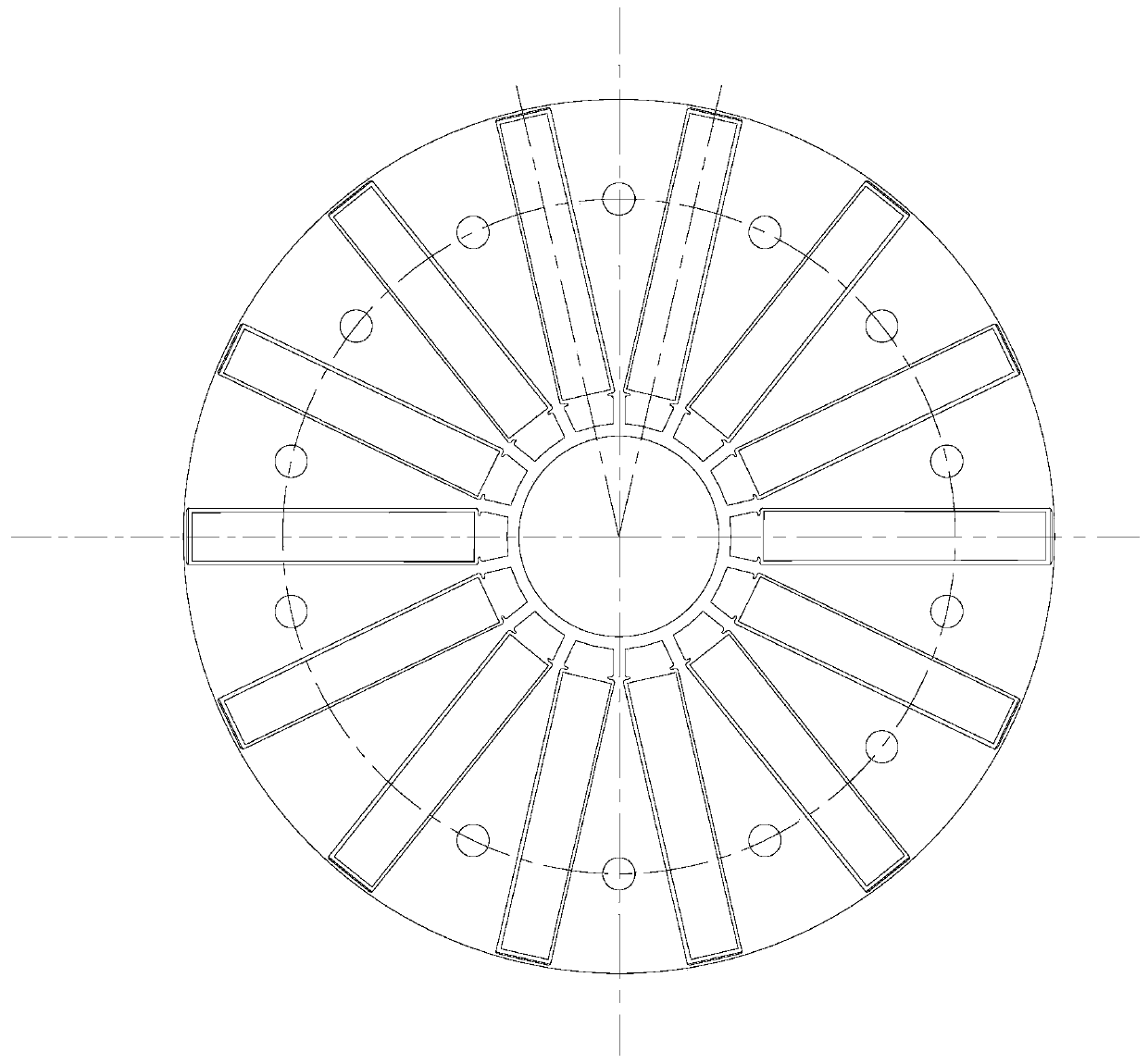
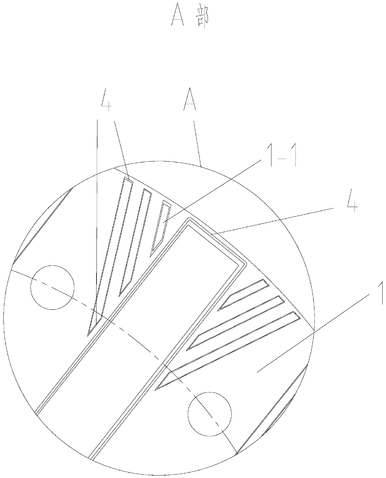
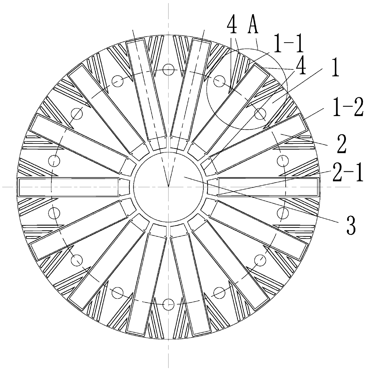
[0019] Such as figure 2 , 3 As shown, a rotor structure of a built-in permanent magnet motor includes an electromagnetic steel plate 1 and a plurality of permanent magnets 2 stacked in the axial direction. The number of magnetic poles is the same as that of the permanent magnets 2. Magnet holes 1-2, a plurality of permanent magnets 2 are installed in the permanent magnet holes 1-2, and the center of the electromagnetic steel plate 1 has a shaft hole 3, which is characterized in that the magnetization direction of the permanent magnets 2 is tangential and adjacent The magnetization direction of the permanent magnet is opposite. On the electromagn...


PUM

PropertyMeasurementUnit
Thicknessaaaaaaaaaa

Abstract

The invention discloses a built-in permanent magnet motor rotor structure. The motor rotor comprises an electromagnetic steel plate and a plurality of permanent magnets which are stacked in the axialdirection. The number of the magnetic poles is the same as that of the permanent magnets, a plurality of permanent magnet holes are formed in the electromagnetic steel plate, a plurality of permanentmagnets are arranged in the permanent magnet holes, and a shaft hole is formed in the center of the electromagnetic steel plate. The innovation points of built-in permanent magnet motor rotor structure are as follows: the magnetizing directions of the permanent magnets are tangential, the magnetizing directions of the adjacent permanent magnets are opposite, a plurality of magnetism isolating slender holes are formed in the electromagnetic steel plate between the adjacent magnetic poles, and the magnetism isolating slender holes are parallel to a d-axis magnetic circuit and vertical to a q-axis magnetic circuit. The built-in permanent magnet motor rotor structure has the characteristics of good magnetism gathering effect and improved power factor.

Description

technical field [0001] The invention relates to the field of motors, in particular to a built-in permanent magnet motor rotor structure. Background technique [0002] The mainstream structure of the current magnetism-concentrating permanent magnet motor rotor is as follows: figure 1 As shown, the permanent magnets are radially embedded in the square holes of the punched silicon steel sheets. The magnetization direction of the permanent magnets is tangential, and the magnetization directions of adjacent permanent magnets are opposite, so the magnetic circuit gathers between the magnetic poles and the direction is determined by The tangential direction is changed to the radial direction, so that the outer circle appears as N, S, N, S alternating magnetic poles; this structure has two disadvantages: (1) The magnetic field wave of the outer circle forms a square wave, and after Fourier decomposition There will be a lot of harmonics, which not only increase the iron loss of the ...

Claims


Application Information

Patent Timeline
IPC IPC(8): H02K1/27H02K29/03
CPCH02K1/27H02K1/276H02K2213/03H02K29/03
Inventor 何圣洪
Owner CHANGZHOU HONGHUI POWER TECH
Features
  • R&D
  • Intellectual Property
  • Life Sciences
  • Materials
  • Tech Scout
  • Unparalleled Data Quality
  • Higher Quality Content
  • 60% Fewer Hallucinations
Learn More