
AC stacked power amplifier

A technology for power amplifiers and transformers, applied in amplifiers, amplifiers with semiconductor devices/discharge tubes, electrical components, etc., can solve the problem of high power and high efficiency output difficulties, limited high power, high efficiency capabilities, high power, Problems such as limited high-efficiency capabilities can achieve the effect of increasing gain and power capacity, improving efficiency indicators, and improving gain and efficiency indicators

Pending Publication Date: 2020-03-27
QINGHAI UNIV FOR NATITIES
View PDF0 Cites 5 Cited by
  • Summary
  • Abstract
  • Description
  • Claims
  • Application Information

AI Technical Summary

Problems solved by technology

[0003] (1) High power and high efficiency capabilities are limited: typical power amplifiers use a multi-channel parallel combination structure or a distributed structure. The combination efficiency of these two structures is limited, resulting in part of the power loss in the combination network, which limits high power. , high efficiency capability
[0004] (2) The low voltage amplification capability is limited: in order to increase the output power of the amplifier, a transistor stack structure is often used to increase the bias voltage of the amplifier and at the same time increase the AC voltage swing
The interstage stacking structure of conventional differential stacked transistors is directly connected to DC and AC. This connection structure requires high-voltage power supply, which cannot adapt to the low-voltage power supply trend of today's communication system terminals.
[0005] It can be seen from this that the design difficulties of high-gain and high-power amplifiers based on integrated circuit technology are: high power and high efficiency output is difficult; under the low-voltage power supply requirements of today's communication system terminals, the traditional stacking structure has certain defects and deficiency

Method used


Image

  • AC stacked power amplifier
  • AC stacked power amplifier

Examples


Embodiment Construction

[0020] Exemplary embodiments of the present invention will now be described in detail with reference to the accompanying drawings. It should be understood that the implementations shown and described in the drawings are only exemplary, intended to explain the principle and spirit of the present invention, rather than limit the scope of the present invention.

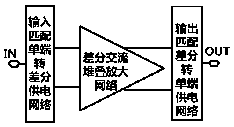
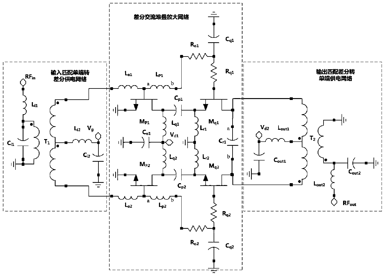
[0021] An embodiment of the present invention provides an AC stack power amplifier, including an input matching single-end to differential power supply network, a differential AC stacking amplification network, and an output matching differential to single-end power supply network.

[0022] Such as figure 1 As shown, the input end of the input matching single-ended to differential power supply network is the input end of the entire power amplifier, its first output end is connected to the first input end of the differential AC stacking amplification network, and its second output end is connected to the The second input...


PUM


Abstract

The invention discloses an alternating current stacked power amplifier. The power amplifier comprises an input matching single-ended-to-differential power supply network, a differential alternating-current stacked amplification network and an output matching differential-to-single-ended power supply network. According to the invention, the core architecture adopts the differential alternating current stacked amplification network, so that the characteristics of high power and high gain at low power supply voltage are realized; and meanwhile, the good parasitic parameter inhibition of the differential amplifier in the microwave frequency band is combined with the power synthesis characteristic of the transformer network, so that the whole power amplifier obtains good high gain, high efficiency and high power output capability.

Description

technical field [0001] The invention relates to the fields of field effect transistor radio frequency power amplifiers and integrated circuits, in particular to an AC stacking power amplifier applied to a transmitting module of a radio frequency microwave terminal transceiver. Background technique [0002] With the rapid development of wireless communication systems and RF microwave circuits, RF front-end transceivers are also developing in the direction of high performance, high integration, and low power consumption. Therefore, the market urgently needs the radio frequency and microwave power amplifier of the transmitter to have high output power, high gain, high efficiency, low cost and other performances. However, when using integrated circuit technology to design and implement RF and microwave power amplifier chip circuits, its performance and cost are subject to certain constraints, mainly reflected in: [0003] (1) High power and high efficiency capabilities are limi...

Claims


Application Information

Patent Timeline
IPC IPC(8): H03F3/217
CPCH03F3/217
Inventor 林倩邬海峰陈善继陈聪
Owner QINGHAI UNIV FOR NATITIES
Learn More