Liquid chip separation device for processing center
A machining center and separation device technology, applied in metal processing equipment, metal processing machinery parts, manufacturing tools, etc., can solve the problems of reducing the service life of the net liquid pump, reducing the service life of the tool, and the wear of the net liquid pump, so as to simplify the operation , Reduce downtime, fully utilize the effect of parts
- Summary
- Abstract
- Description
- Claims
- Application Information
AI Technical Summary
Problems solved by technology
Method used
Image

Examples
Embodiment 1
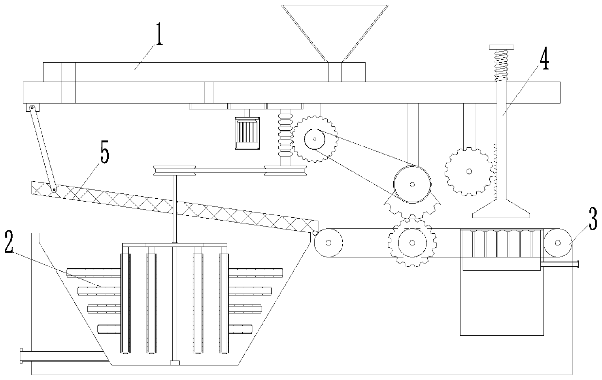
[0029] refer to figure 1 , the present invention proposes a liquid chip separation device for machining centers, the device includes a feed unit 1, a solid-liquid separation unit and a waste treatment unit 4, the feed unit 1 is used for feeding intermittently, the solid-liquid The separation unit is used to realize the separation of waste chips and cutting fluid, and the waste chip processing unit 4 is used to apply pressure to the separated waste chips.
[0030] refer to Figure 4 , the feeding unit 1 includes a hopper 11, the hopper 11 is used to hold waste chips generated by machining and cutting fluid used for cooling and lubricating the cutting tool. The materials in the hopper 11 can fall to the solid-liquid separation unit by gravity, and the solid-liquid separation unit can realize the automatic separation of waste chips and cutting fluid.
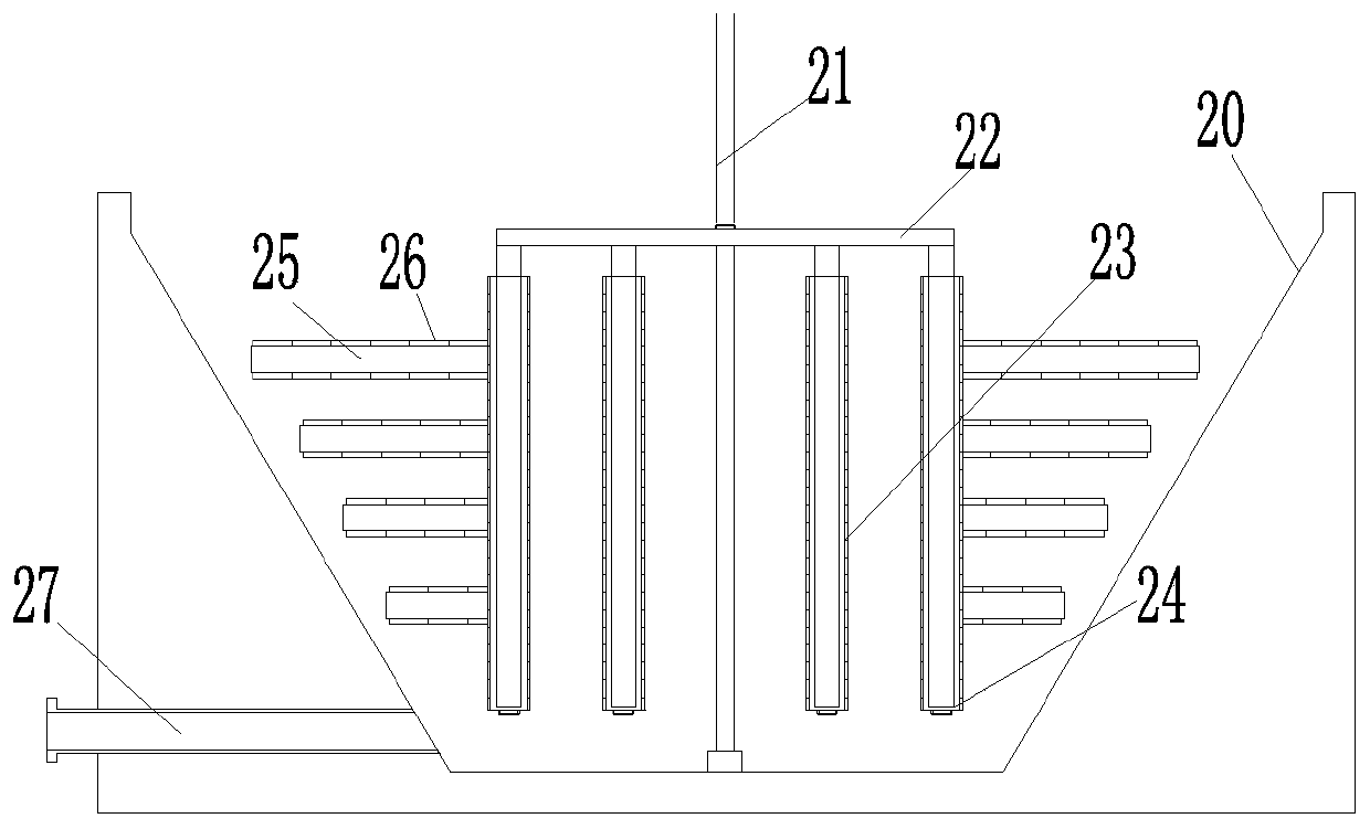
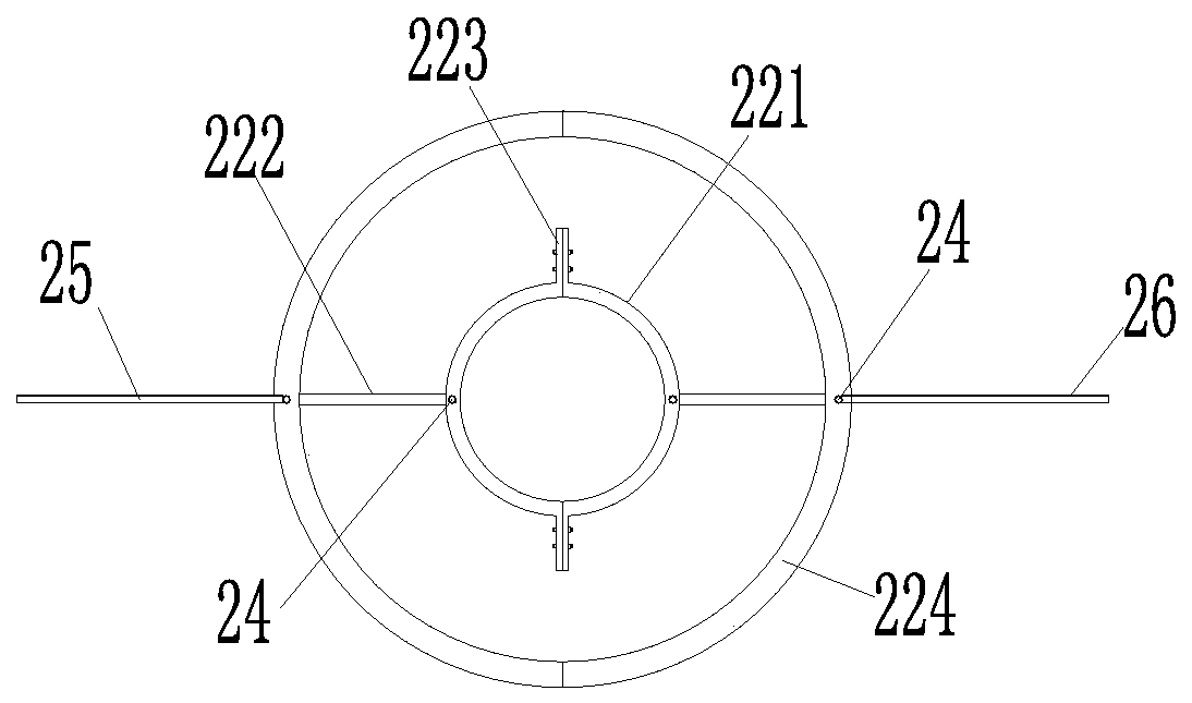
[0031] refer to Figure 1-4 , the solid-liquid separation unit includes a screening mechanism 6 and a purification mechanism 2...
Embodiment 2
[0042] Conveyor belt 3 can intermittently transmit waste chips. When conveyor belt 3 transmits waste chips to the bottom of pressing plate 43, the movement of conveyor belt 3 stops, and pressing plate 43 moves downward. After contacting waste chips, pressure is gradually applied to waste chips. After the waste chips are extruded, the pressing plate 43 is reset, and the conveyor belt 3 continues to move, so as to convey the extruded waste chips and re-transmit the waste chips to be processed to the bottom of the pressing plate 43 .
[0043] The difference between this embodiment and the above-mentioned embodiment is: refer to Figure 4 , the conveyor belt 3 is mounted on a driving wheel 32 and two driven wheels 31, the driving wheel 32 is located between the two driven wheels 31, and the driving wheel 32 is connected to the vertical shaft 15 through a first transmission mechanism. The first transmission mechanism includes a worm 151, a worm wheel, a third roller 35, a fourth ro...
Embodiment 3
[0047] The difference between this embodiment and the above-mentioned embodiment is: refer to Figure 5 , the support plate 13 is penetratingly provided with a shaft hole, the shaft hole is pierced with a lifting shaft 46, the upper end of the lifting shaft 46 is fixedly mounted with a top plate 45, and a set is provided between the top plate 45 and the lifting plate A spring 44, the spring 44 is sleeved on the lifting shaft 46, the pressing plate 43 is fixedly installed on the lifting shaft 46, and the lifting shaft 46 is driven to move by the second transmission mechanism. The second transmission mechanism includes a rack 42 and a fourth gear 41, the rack 42 is installed on the lower end of the lifting shaft 46, the pressing plate 43 is installed on the lower end of the rack 42, the rack 42 Intermeshing with the fourth gear 41 , the fourth gear 41 is rotatably connected to the support plate 13 and intermittently meshes with the sector gear 34 .
[0048] After the teeth of t...
PUM
 Abstract
Description
Claims
Application Information
 - R&D
- Intellectual Property
- Life Sciences
- Materials
- Tech Scout
- Unparalleled Data Quality
- Higher Quality Content
- 60% Fewer Hallucinations
Browse by: Latest US Patents, China's latest patents, Technical Efficacy Thesaurus, Application Domain, Technology Topic, Popular Technical Reports.
© 2025 PatSnap. All rights reserved.Legal|Privacy policy|Modern Slavery Act Transparency Statement|Sitemap|About US| Contact US: help@patsnap.com