Dispensing subsequent glue removing device for electronic component

A technology for electronic components and dispensing, which is used in grinding drive devices, grinding/polishing safety devices, grinding workpiece supports, etc. problems, to achieve the effect of increasing the glue removal efficiency, strong practicability and reasonable structure

Active Publication Date: 2020-03-31
肇庆益华电子科技有限公司
View PDF7 Cites 8 Cited by
  • Summary
  • Abstract
  • Description
  • Claims
  • Application Information

AI Technical Summary

Problems solved by technology

[0004] Dispensing electronic components can play the role of moisture-proof, dust-proof, anti-corrosion, shockproof, and improve the performance and stability parameters, but the glue is easy to fly out during the dispensing process, so that the glue sticks to the workbench and solidified on the workbench, which may affect the operation of people using the workbench for dispensing, affect the performance of electronic components, and make the workbench inconvenient to use
Chinese patent (notification number: CN206854007U) discloses a workbench scraping device for dispensing electronic components, including side plates, top plates, geared motors, rotating shafts, gears, bearing seats, racks, poles, handles, sliders, etc. Rail, slide block, connecting rod, first cylinder, swing rod and scraper, the upper part of the side plate has a through hole, the top left side of the side plate is connected with the top plate by bolt connection, and the top of the top plate is connected by bolt connection. The handle and the right side of the bottom of the top plate are connected with a geared motor through a bolt connection, and the output shaft of the geared motor is connected with a rotating shaft through a coupling. Although this device can remove the glue on the electronic components after dispensing to a certain extent, However, in actual operation, the glue cannot be effectively removed, and there will still be a large amount of residue left on the electronic components. Therefore, further improvement is still needed.

Method used


Image

  • Dispensing subsequent glue removing device for electronic component
  • Dispensing subsequent glue removing device for electronic component
  • Dispensing subsequent glue removing device for electronic component

Examples


Embodiment 1

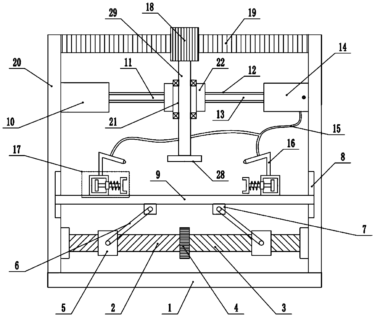
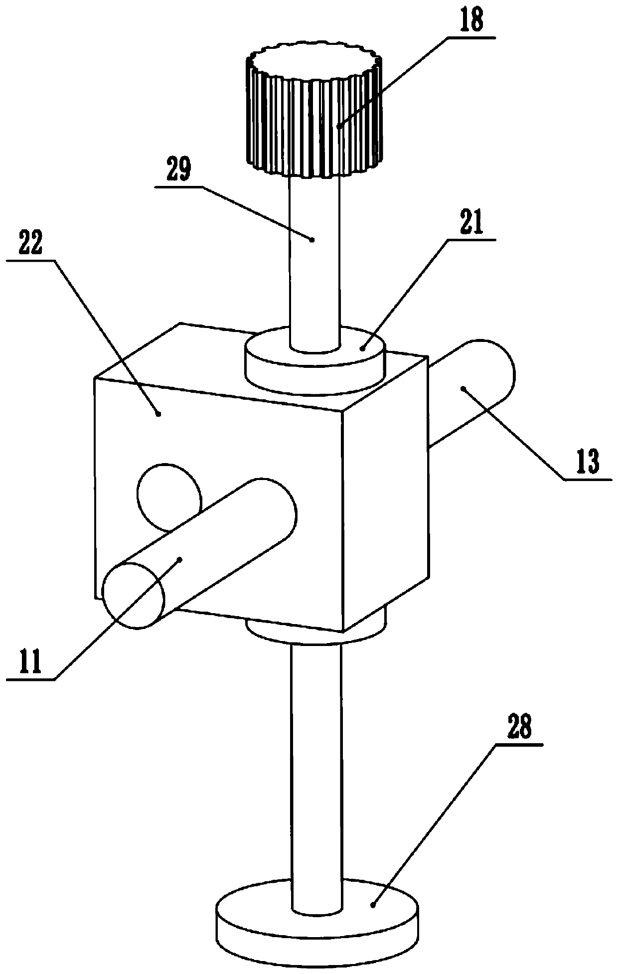
[0028] refer to Figure 1~3 , in an embodiment of the present invention, a dispensing and subsequent glue removal device for electronic components includes a fixed bottom plate 1, a support frame 20 is installed on both sides of the upper end of the fixed bottom plate 1, and a fixed rack 19 is installed on the top of the support frame 20, A guide column 12 is installed between the upper ends of the support frame 20, and the middle part of the guide column 12 is slidably connected with a sliding block 22. The sliding block 22 can move left and right along the guide column 12, and a bearing seat 21 is installed inside the sliding block 22, and the bearing seat 21 A rotating shaft 29 is installed inside, and the rotating shaft 29 can rotate along the bearing seat 21. The upper end of the rotating shaft 29 is equipped with a movable gear 18 that meshes with the fixed rack 19, and the bottom end of the rotating shaft 29 is equipped with a glue removal grinding wheel 28. The glue re...

Embodiment 2

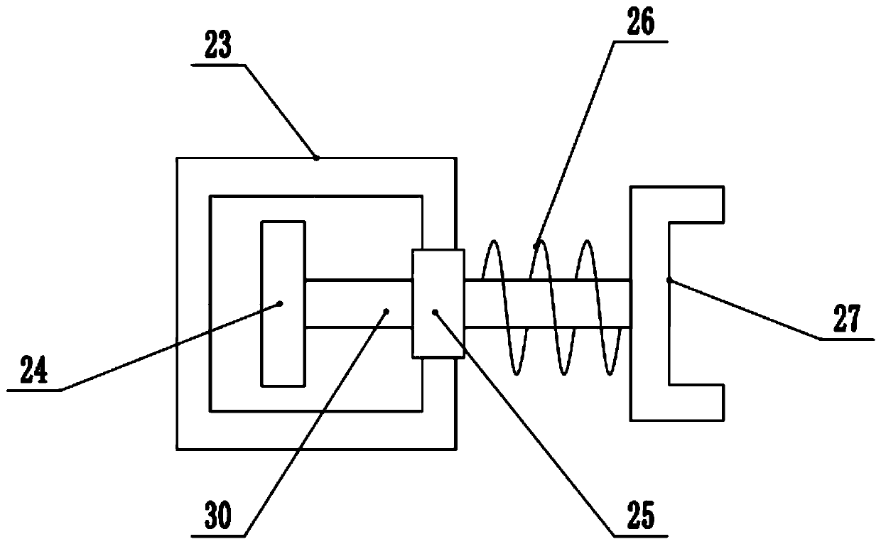
[0030] In another embodiment of the present invention, the difference between this embodiment and the above embodiment is that the positioning and clamping mechanism 17 includes a fixed frame 23, a guide block 25 is installed in the middle of the fixed frame 23, and a clip is installed in the middle of the guide block 25. Clamping rod 30, clamping rod 30 inboard positioning frame 27 is installed, and baffle plate 24 is installed on the outside of described clamping rod 30, and clamping rod 30 outside between described positioning frame 27 and guide block 25 is provided with spring 26, and described The clamping rod 30 can move left and right along the guide block 25 , and can be limited left and right under the action of the spring 26 , so as to remove glue from the electronic components that need to be glued.

[0031]In the present invention, when working, the electronic components are placed on the positioning frame 27 on the positioning and clamping mechanism 17, and the cla...


PUM


Abstract

The invention relates to a machining device for electronic components and discloses a dispensing subsequent glue removing device for an electronic component, which comprises a fixed bottom plate. Support frames are mounted on two sides of the upper end of the fixed bottom plate; a fixed rack is installed at the top of the support frame; a guide column is arranged between the upper ends of the support frames; a sliding block is slidably connected to the middle of the guide column; a bearing seat is arranged in the sliding block; a rotating shaft is mounted in the bearing seat; a movable gear meshed with the fixed rack is mounted at the upper end of the rotating shaft; a glue removing grinding wheel is arranged at the bottom end of the rotating shaft; an air guiding box is installed in the middle of the left end of the support frame on the right side; a piston plate is installed in the air guiding box; an air guiding rod is installed on the left side of the piston plate; a sliding blockis connected to the left side of the air guiding rod; a lifting plate is installed between the inner sides of the support frames; and positioning clamping mechanisms are installed on the two sides ofthe upper end of the lifting plate. Reciprocating rotation of the glue removing grinding wheel is achieved, the glue removing efficiency of the electronic components is greatly improved, meanwhile, glue residues obtained after glue removing can be better blown away, and the glue removing efficiency is further improved.

Description

technical field [0001] The invention relates to a processing device for electronic components, in particular to a glue dispensing and subsequent glue removal device for electronic components. Background technique [0002] Electronic components are components of electronic components and small electrical machines and instruments. They are often composed of several parts and can be used in similar products; they often refer to certain parts in industries such as electrical appliances, radios, and instruments, such as capacitors and transistors. The general term for hairsprings, springs and other sub-devices, such as diodes are common. [0003] Electronic components include: resistors, capacitors, potentiometers, electron tubes, radiators, electromechanical components, connectors, semiconductor discrete devices, electroacoustic devices, laser devices, electronic display devices, optoelectronic devices, sensors, power supplies, switches, micro-motors , electronic transformers, ...

Claims


Application Information

Patent Timeline
Patent Type & Authority Applications(China)
IPC IPC(8): B24B27/033B24B41/06B24B47/12B24B47/16B24B55/06
CPCB24B27/033B24B41/06B24B47/12B24B47/16B24B55/06
Inventor 徐尚
Owner 肇庆益华电子科技有限公司
Why Eureka
Try Eureka