Annular arrangement route mining method

A mining method and a technology of circular arrangement, applied in the field of model tests, can solve the problems of reduced mining quantity, poor ventilation effect of approach mining, and unstable strength of cemented filling body, etc., and achieve high safety production factor and poor loss. The effect of low rate and small exposed area

Active Publication Date: 2020-03-31
甘肃省合作早子沟金矿有限责任公司
View PDF5 Cites 7 Cited by
  • Summary
  • Abstract
  • Description
  • Claims
  • Application Information

AI Technical Summary

Problems solved by technology

[0005] For this reason, the embodiment of the present invention provides a mining method with circular layout approach, which solve

Method used


Image

  • Annular arrangement route mining method
  • Annular arrangement route mining method
  • Annular arrangement route mining method

Examples


Embodiment 1

[0049]The present invention provides a mining method with circular arrangement approach, comprising the steps of:

[0050] S100. Construct the main contact road, the left stope contact road, and the right stope contact road to find out the ore body according to a certain distance;

[0051] S200. In the delineated ore body, along the left and right sides of the stope main contact road, excavation along the vein is carried out in parallel according to a certain interval, respectively connected with the left stope contact road and the right stope contact road, and the construction cutting work reaches the one-step road specification;

[0052] Before carrying out S200, it is necessary to determine the safety production specifications of the route.

[0053] S300. Construct a vertical ventilation and drainage well upward at the centerline position of the approach at the intersection of the left stope access road and the right stope access road; construct concrete at the intersection...

Embodiment 2

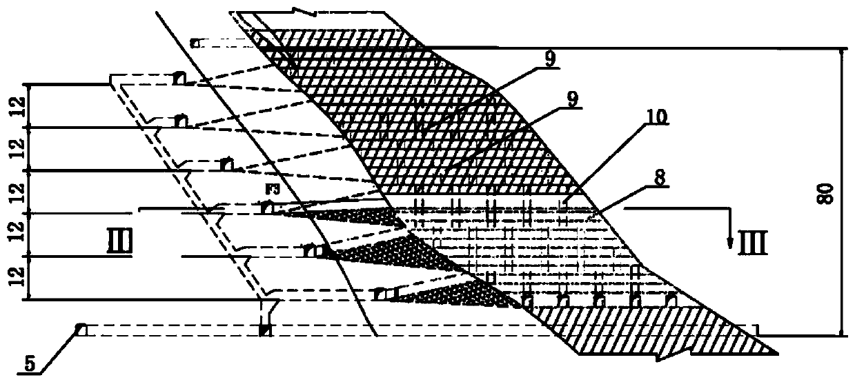
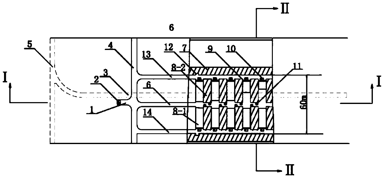
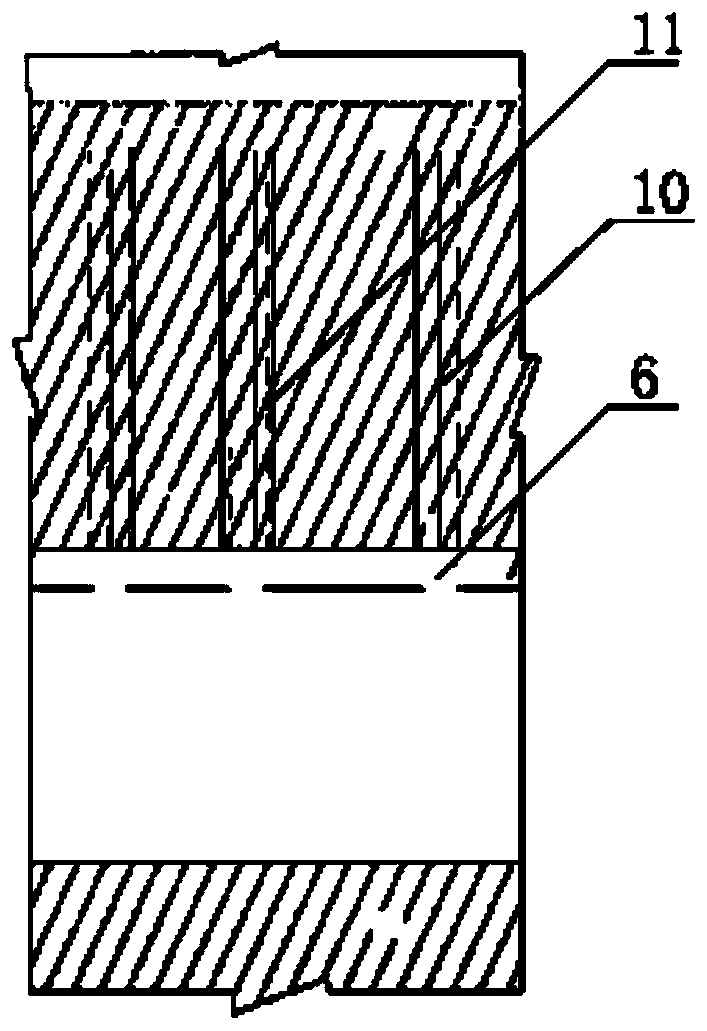
[0071] combine figure 1 , figure 2 as well as image 3 As shown, take the stope mining of line 54-55 in the middle section of -140 in a certain mining area as an example:

[0072] Step 1. Construct three stope access roads 6 along the segmented roadway 4 at a certain interval to find out the ore body. The specifications of the stope access roads 6 are all 3.6m*3.2m. Shovel into mine shaft 2;

[0073] Step 2. Open in the delineated ore body along the main contact road 6 of the stope at intervals of 10m, and excavate along the vein parallel to the direction of the ore body. The connecting road 14 is connected, and the excavation brush of the stepping road 8-1 is enlarged to the specification of 5.0m*3.8m;

[0074] Step 3. Construct a vertical ventilation and drainage well 10 upwards at the top plate at the central line position of the approach at the intersection of the left stope connecting road 13 and the right stope connecting road 14. The length of the ventilation and d...


PUM

PropertyMeasurementUnit
Specificationaaaaaaaaaa

Abstract

The embodiment of the invention discloses an annular arrangement route mining method which is suitable for medium-thick ore bodies and above. The construction steps are as follows: three stope main connecting roadways are constructed in a delineated ore body, a first-step route is constructed to a left stope connecting roadway and a right stope connecting roadway along the position of the stope main connecting roadways parallel to the trend of the ore body, and a second-step route is constructed to the stope main connecting roadways along the boundaries of a left stope and a right stope; the first-step route is provided with a special cemented filling drainage well, the second-step route is provided with a reserved special ventilation well, and a graded tailings filling process is adopted;the route mining sequence, filling, ventilation and other processes of an upper section and a lower section are exchanged, the workload of stope preparation is reduced until stope coal extraction isfinished, alternate roof-contact filling upward mining of the first-step route and the second-step route of the stope is carried out, and the undercutting work quantity is reduced; and graded tailingsfilling and cemented filling are constructed alternately, and the advantages that the filling cost is reduced, the labor efficiency is high, the stope preparation work amount is relatively small, thestrength of a filling body is high, and the ventilation effect is good are achieved.

Description

technical field [0001] The embodiments of the present invention relate to the technical field of model testing, and in particular to a mining method with circularly arranged routes. Background technique [0002] With the gradual development of mining technology, there are many kinds of mining methods for metal and non-metal mines. The existing mining methods have their own advantages: on the one hand, they can ensure high-efficiency production, such as deep hole, medium and deep hole falling ore, and the amount of mining work is small. However, the problems of safety and the high rate of loss and dilution have not been resolved; on the one hand, it focuses on reducing the rate of loss and dilution to ensure safe production, especially in precious and high-grade metal and non-metal mines, such as shallow hole stratification Falling ore, but the production efficiency is low. [0003] The access mining method is a relatively mature mining technology at present. Due to the smal...

Claims


Application Information

Patent Timeline
IPC IPC(8): E21C41/22E21D9/14E21F15/00E21F15/04
CPCE21C41/22E21D9/14E21F15/00E21F15/04Y02A30/60
Inventor 郭俊利郝忠林杨桂涛
Owner 甘肃省合作早子沟金矿有限责任公司
Why Eureka
Try Eureka