
Method and system for measuring highly reflective objects based on laser speckle limit-constrained projection

A technology of extreme constraints and laser speckle, applied in the direction of measuring devices, optical devices, instruments, etc., can solve the problems of three-dimensional measurement of highly reflective objects, complex measurement system, and difficulty in implementation, so as to improve the accuracy of three-dimensional measurement and reduce the impact , the effect of simple structure

Active Publication Date: 2021-03-30
BEIJING INSTITUTE OF TECHNOLOGYGY
View PDF7 Cites 0 Cited by
  • Summary
  • Abstract
  • Description
  • Claims
  • Application Information

AI Technical Summary

Problems solved by technology

This method can geometrically analyze the light transmission process, but this method needs to maintain the temporal and spatial synchronization of the mask in front of the projector and the camera, and its hardware equipment needs special modulation, which makes the measurement system very complicated and difficult. accomplish
[0005] The difficulty of measuring highly reflective objects is that the receiver receives the information after light aliasing on the surface of highly reflective objects, and cannot perform correct three-dimensional measurement of highly reflective objects. In order to solve the shortcomings of the existing technology, it is necessary to study a structure A design system that is simple, has high precision, and has certain versatility, and can eliminate the influence of light refraction and aliasing on the surface of highly reflective objects

Method used

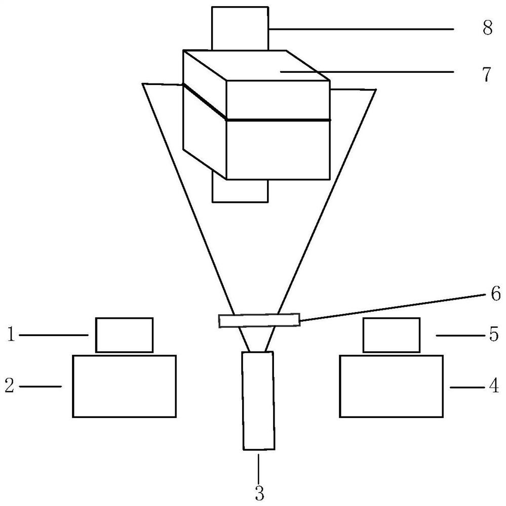

Image

  • Method and system for measuring highly reflective objects based on laser speckle limit-constrained projection
  • Method and system for measuring highly reflective objects based on laser speckle limit-constrained projection
  • Method and system for measuring highly reflective objects based on laser speckle limit-constrained projection

Examples


Embodiment Construction

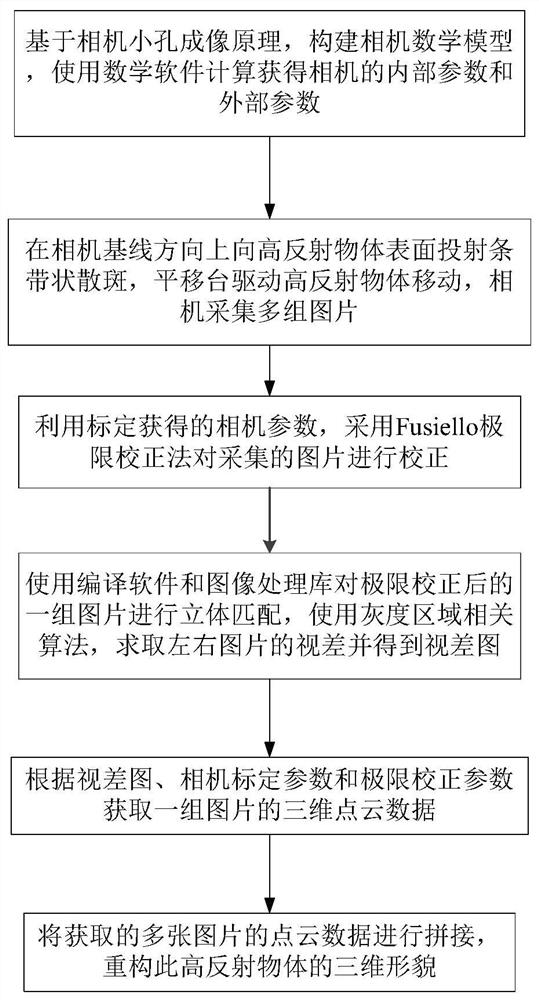
[0020] Such as figure 1 As shown in , this method of measuring highly reflective objects based on laser speckle limit-constrained projection includes the following steps:

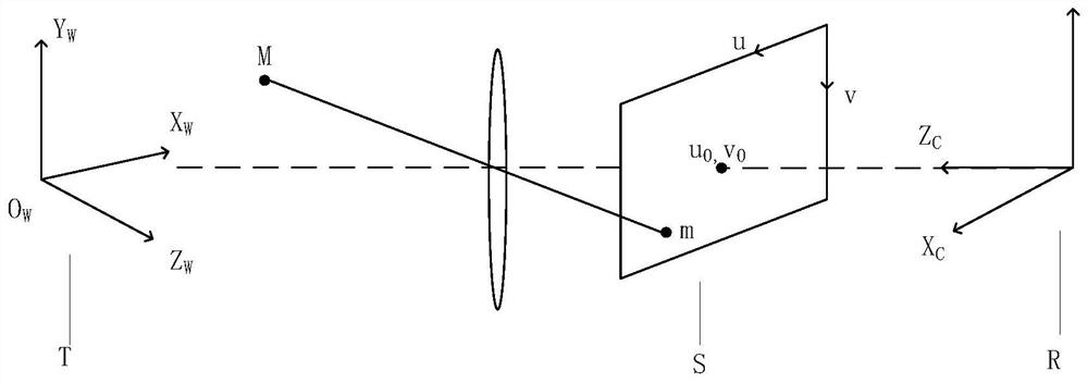
[0021] (1) Based on the principle of camera pinhole imaging, construct a mathematical model of the camera, and use mathematical software to calculate the internal and external parameters of the camera;

[0022] (2) Project stripe-shaped speckle on the surface of the highly reflective object in the direction of the camera baseline, the translation stage drives the highly reflective object to move, and the camera collects multiple sets of pictures;

[0023] (3) Utilize the camera parameters obtained in step (1) to calibrate, and use the Fusiello limit correction method to correct the pictures collected in step (2);

[0024] (4) Use compiling software and image processing library to carry out stereo matching to a group of pictures after step (2) limit correction, use gray scale area correlation algorithm, ask...


PUM


Abstract

The invention discloses a high-reflection object measurement method and system based on laser speckle limit constraint projection. Measurement of a high-reflection object can be completed accurately only by simple laser emission and image acquisition equipment. The system is simple in structure, an anti-reflection material does not need to be smeared or contact type measurement does not need to beadopted, it is guaranteed that a measured object is not damaged, certain universality is achieved for measurement of common objects in industrial life, influences brought by reflection light of a high-reflection object are effectively reduced, and the three-dimensional measuring precision of the reflection object is improved. The method comprises the following steps: (1) constructing a camera mathematical model to obtain internal parameters and external parameters of a camera; (2) projecting strip-shaped speckles to the surface of the high-reflection object in the baseline direction of the camera, driving the object to move by a translation stage, and acquiring multiple groups of pictures by the camera; (3) carrying out correction by adopting a Fusiello limit correction method; (4) carrying out the stereo matching to solve the parallax of the left and right pictures and to obtain a parallax graph; (5) acquiring three-dimensional point cloud data; and (6) reconstructing the three-dimensional shape of the object.

Description

technical field [0001] The invention relates to the technical field of optical three-dimensional measurement, in particular to a method for measuring highly reflective objects based on laser speckle limit-constrained projection and a system for measuring high-reflection objects based on laser speckle limit-constrained projection. Background technique [0002] In the field of three-dimensional measurement, optical three-dimensional measurement technology has the advantages of non-contact measurement, fast speed, high accuracy and high degree of automation, and is widely used in machine vision, reverse engineering, medical diagnosis and medical cosmetology, anthropometric measurement, manufacturing industry, etc. field and made great progress. However, in industry and daily life, there are a large number of highly reflective objects, such as ceramic products, metal parts, etc. The surface reflectance of such objects to be measured varies in a wide range, and traditional optica...

Claims


Application Information

Patent Timeline
Patent Type & Authority Patents(China)
IPC IPC(8): G01B11/25
CPCG01B11/254
Inventor 张韶辉郝群王云梅胡摇
Owner BEIJING INSTITUTE OF TECHNOLOGYGY
Learn More