Integrated weak light triggering gas switch circuit based on transformer and working method thereof

A technology of gas switch and transformer, which is applied in the field of integrated weak light trigger gas switch circuit, can solve the problems of increased complexity, lower reliability of gas switch trigger, large trigger light energy, etc., to achieve reduced volume and easy control of trigger time Effect

Pending Publication Date: 2020-03-31
INST OF FLUID PHYSICS CHINA ACAD OF ENG PHYSICS
View PDF0 Cites 1 Cited by
  • Summary
  • Abstract
  • Description
  • Claims
  • Application Information

AI Technical Summary

Problems solved by technology

The advantage of electric pulse triggering is that the circuit is simple and the cost is low. The disadvantage is that the trigger pulse generator is large in size, the volume of the whole system and the complexity of control are significantly increased when multi-channel gas switches are triggered, and the synchronization of multiple outputs is relatively poor. The advantages of direct laser triggering are good switch synchronization, photoelectric isolation between trigger control and high voltage, etc., but its disadvantages are that it requi

Method used


Image

  • Integrated weak light triggering gas switch circuit based on transformer and working method thereof

Examples


Embodiment 1

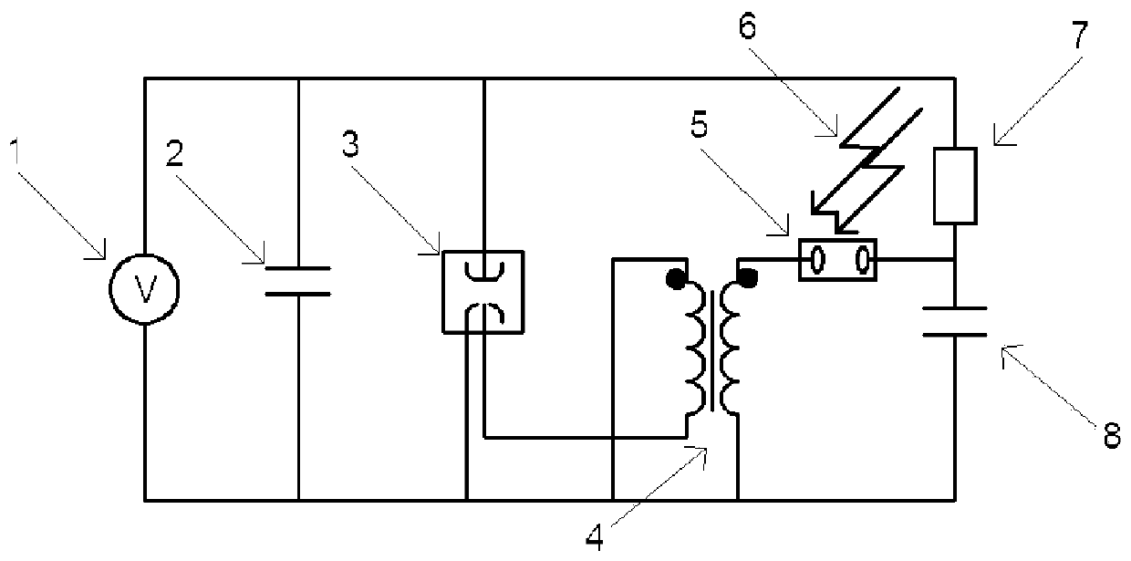
[0035] Such as figure 1 As shown, the integrated low-light trigger gas switch 3 circuit based on the transformer 4, the gas switch 3, the transformer 4, the photoconductive switch 5, the voltage dividing resistor 7 and the trigger capacitor 8;

[0036] The high voltage pole of the gas switch 3 is connected to the voltage dividing resistor 7, the ground electrode of the gas switch 3 is grounded, and the trigger pole of the gas switch 3 is connected to the secondary side of the transformer 4;

[0037] One terminal on the primary side of the transformer 4 is connected to one end of the photoconductive switch 5, and the other end of the photoconductive switch 5 is respectively connected to a voltage dividing resistor 7 and a trigger capacitor 8, and the trigger capacitor 8 and the voltage dividing resistor 7 form an RC voltage divider circuit; by adjusting The component parameters of the RC voltage divider circuit are used to adjust the preset value of the trigger component; the o...

Embodiment 2

[0040]In this embodiment, the high voltage pole of the gas switch 3 and the voltage dividing resistor 7 are connected to the positive pole of a main circuit power supply 1 , and the negative pole of the main circuit power supply 1 is grounded; the main circuit power supply 1 is connected in parallel with a main energy storage capacitor 2 . The trigger capacitor 8 is connected to the gas switch 3 and the main circuit power supply 1 through the voltage dividing resistor 7, and the trigger circuit can directly obtain the voltage and energy required for the trigger system from the main circuit or the electric field of the gas switch 3 without adding a charging power supply to the trigger circuit. The volume and circuit complexity of the switching system can be reduced.

[0041] The photoconductive switch 5 works in a nonlinear working mode. The photoconductive switch 5 is in a non-linear working mode, and the required triggering light energy is only a few microjoules to tens of mi...

Embodiment 3

[0046] In this embodiment, the main circuit power supply 1 charges the main energy storage capacitor 2 with a capacity of 22nF to 50kV, and the charging time is 30 microseconds, and the self-breakdown voltage of the gas switch 3 connected in parallel with the main energy storage capacitor 2 is about 65kV , the voltage dividing resistor 7 is a 20kΩ high-voltage glass glaze resistor, and the trigger energy storage capacitor is a high-voltage ceramic capacitor with a capacity of 3.3nF and a withstand voltage of 15kV. Therefore, the voltage of the trigger energy storage capacitor is 8kV 30 microseconds after the start of charging, and the conduction The component (photoconductive switch 5) is a GaAs semi-insulated photoconductive switch 5 with a length, width, and height of 6mm×6mm×3mm placed in insulating oil. The pass element makes it enter the conduction state, so that the capacitor connected to the trigger energy storage discharges the primary side of the transformer 4, and the...


PUM

PropertyMeasurementUnit
Divider resistoraaaaaaaaaa

Abstract

The invention discloses an integrated weak light triggering gas switch circuit based on a transformer, and a working method thereof. The circuit comprises a gas switch, a transformer, a photoconductive switch, a divider resistor and a trigger capacitor, the high-voltage electrode of the gas switch is connected with the divider resistor, the ground electrode of the gas switch is grounded, and the trigger electrode of the gas switch is connected with the secondary side of the transformer; one terminal of the primary side of the transformer is connected with one end of the photoconductive switch,and the other end of the photoconductive switch is connected with the divider resistor and the trigger capacitor. And the other terminal of the primary side of the transformer is connected with the trigger capacitor and grounded. According to the invention, micro-focus low-energy laser triggering, triggering control and high voltage can be adopted to realize photoelectric isolation; optical fibers are used for transmitting trigger light energy, complex collimation, light alignment and other operations are omitted, and the trigger moment is easy to control. The trigger loop directly obtains the voltage and the energy required by the trigger system from the main loop or the gas switch electric field, and a charging power supply does not need to be additionally arranged.

Description

technical field [0001] The invention relates to the technical field of switches and their triggers in pulse power technology, in particular to a transformer-based integrated weak-light trigger gas switch circuit and its working method. Background technique [0002] The switch is one of the key components of the pulse power device, and its performance has an important influence on the performance of the pulse power device. Gas switch is the most commonly used switch in pulse power devices, and its common trigger methods are electric pulse trigger and laser direct trigger. The advantage of electric pulse triggering is that the circuit is simple and the cost is low. The disadvantage is that the trigger pulse generator is large in size, the volume of the whole system and the complexity of control are significantly increased when multi-channel gas switches are triggered, and the synchronization of multiple outputs is relatively poor. The advantages of direct laser triggering are...

Claims


Application Information

Patent Timeline
IPC IPC(8): H03K17/687
CPCH03K17/687
Inventor 付佳斌谢卫平王凌云冯传均何泱
Owner INST OF FLUID PHYSICS CHINA ACAD OF ENG PHYSICS
Why Eureka
Try Eureka