End-to-end transmission delay measurement method and system for low-voltage power distribution network

A low-voltage distribution network and transmission delay technology, applied in distribution line transmission systems, transmission systems, wired transmission systems, etc., can solve the problems of measurement failure, inappropriate transmission delay measurement, impedance discontinuity, etc. Improved stability, good anti-interference, guaranteed effectiveness and accuracy

Active Publication Date: 2020-03-31
CHINA GRIDCOM
View PDF6 Cites 1 Cited by
  • Summary
  • Abstract
  • Description
  • Claims
  • Application Information

AI Technical Summary

Problems solved by technology

[0007] In the existing second type of system, the radar technology cannot be directly applied to the end-to-end transmission delay measurement of the power line network; the technology in the vector network analyzer must require that the two ends of the cable under test can be placed at the same place, which is obviously not applicable The power line network where each terminal is located in different geographical locations; the network cable length tester, cable length tester and optical fiber length tester require that one end of the cable and optical fiber to be tested must be disconnected from the system, and there is only one reflected signal, while a typical power line network, t

Method used


Image

  • End-to-end transmission delay measurement method and system for low-voltage power distribution network
  • End-to-end transmission delay measurement method and system for low-voltage power distribution network
  • End-to-end transmission delay measurement method and system for low-voltage power distribution network

Examples


Example Embodiment

[0046] Example 1

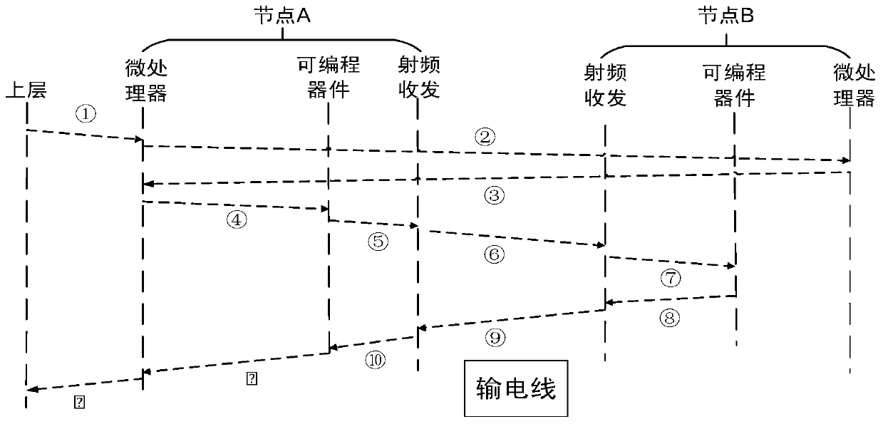
[0047] Such as Figure 2-Figure 3 As shown, the process of the proposed delay measurement system is described as follows:

[0048] ① The upper layer sends a time delay measurement command containing the measured node ID (set as B) to node A through the power line communication module;

[0049] ②The microprocessor of node A sends the time delay measurement command to node B through the power line communication module;

[0050] ③The microprocessor of node B replies to node A through the power line communication module with a measurement confirmation command;

[0051] ④The microprocessor of node A sends the time delay measurement start command to its programmable device;

[0052] ⑤The programmable device of node A generates a measurement signal, sends it to its radio frequency transmitter module, and records the current time t when all the measurement signals are sent. 1 ;

[0053] ⑥The measurement signal sent by node A reaches the radio frequency receiving module of node ...

Example Embodiment

[0062] Example 2

[0063] Adopt BPSK modulation method, carrier frequency is 4MHz, m1 and m2 sequence select 15-bit m code, where m1=[1,-1,-1,1,1,-1,1,-1,1,1,1,1 ,-1,-1,-1],

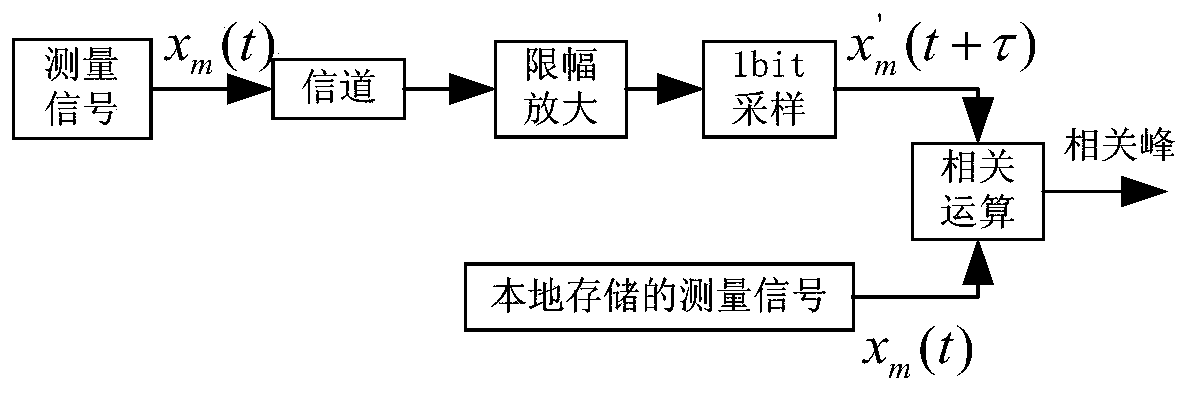
[0064] m2=[1,1,1,1,-1,1,-1,1,1,-1,-1,1,-1,-1,-1]. FPGA adopts EP4CE15, MCU adopts STM32F407, and power line carrier communication module adopts Shenzhen Guodian TXHX13-GD31001 module. The sampling rate frequency of FPGA to spread spectrum signal is 100MHz. The output results of correlation peaks under different noise interference are given. Figure 4 Is the correlation peak without noise and interference, Figure 5 Is the correlation peak when only white noise interference (SNR=-5dB) exists, Image 6 Is the correlation peak when there is only one multipath interference (SIR=5dB), Figure 7 It is the correlation peak when only 4MHz single frequency interference (SIR=0dB) exists.

[0065] Such as Figure 4-7 As shown, since the correlation calculation formulas (2)-(6) are directly performed on the BPSK modulat...


PUM


Abstract

The invention discloses an end-to-end transmission delay measurement method and system for a low-voltage distribution network, and the method comprises the steps that an upper layer transmits a measurement signal to a first microprocessor A1 through a power line and a first power line carrier communication module A3, and the first microprocessor A1 starts a measurement process after receiving themeasurement signal; and a first time signal K1 generated by the first programmable device A2 is transmitted through a first spread spectrum signal transmitter A4. A programmable device records the time t1 at the moment, after the first programmable device A2 receives a second time signal and carries out related operation processing, the time t2 is recorded, and transmission delay t<transmission>=(t2-t1-t<processing>-t<sending duration>)/2, wherein the t<processing> is the time spent in processing various digital signals and is a determined value, the t<sending duration> is the time when the first time signal and the second time signal are transmitted through the spread spectrum signal, is related to the sequence length of K1 and K2 and the data transmission rate and is also a determined value, and thus a determined time delay result is obtained.

Description

technical field [0001] The invention relates to the field of delay measurement, in particular to a method and system for end-to-end transmission delay measurement of a low power distribution network. Background technique [0002] There are three main types of existing transmission delay measurement systems: the first type is a communication-based end-to-end network transmission delay test system, the second type is a transmission delay measurement system based on pulse reflection, and the third type is global satellite positioning system [0003] The first type of system is mainly used in computer network communication end-to-end creation delay test and wireless communication network end-to-end transmission delay test. During delay measurement, the measurement direction sends a data packet to the measured party, and the measured party returns a response packet after receiving the data packet. The measuring party records the time when the data packet is sent and the time wh...

Claims


Application Information

Patent Timeline
IPC IPC(8): H04B3/54H04B3/462H04B3/46
CPCH04B3/542H04B3/462H04B3/46
Inventor 赵成文毛珊珊何先灯陆欣洪海敏冷安辉刘飞飞武兴佩贺竞辉吴锐浩
Owner CHINA GRIDCOM
Why Eureka
Try Eureka