Suction lifting and releasing device for optical lens

An optical lens and mounting frame technology, applied in the directions of transportation and packaging, conveyor objects, furnaces, etc., can solve the problems of easy scratching of the optical lens surface, low work efficiency, manual installation, etc., to reduce workload and improve work efficiency. , the effect of high degree of automation

Inactive Publication Date: 2020-04-03
江西高佳光电科技有限公司
View PDF9 Cites 2 Cited by
  • Summary
  • Abstract
  • Description
  • Claims
  • Application Information

AI Technical Summary

Problems solved by technology

[0004] The purpose of the present invention is to provide a suction and release device for optical lenses, in order to solve the above-mentioned background technology, most of the existing optical lenses installed on the instrument are manually installed, the work efficiency is low, and the surface of the optical lenses is easy to scratch. Problems causing product scrapping

Method used


Image

  • Suction lifting and releasing device for optical lens
  • Suction lifting and releasing device for optical lens
  • Suction lifting and releasing device for optical lens

Examples


Embodiment Construction

[0025] The following will clearly and completely describe the technical solutions in the embodiments of the present invention with reference to the accompanying drawings in the embodiments of the present invention. Obviously, the described embodiments are only some, not all, embodiments of the present invention. The specific embodiments described here are only used to explain the present invention, not to limit the present invention. Based on the embodiments of the present invention, all other embodiments obtained by persons of ordinary skill in the art without making creative efforts belong to the protection scope of the present invention.

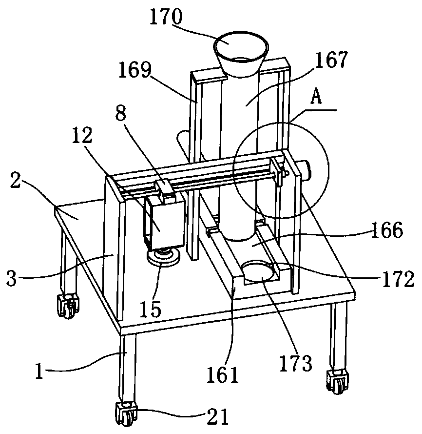
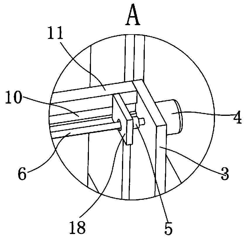
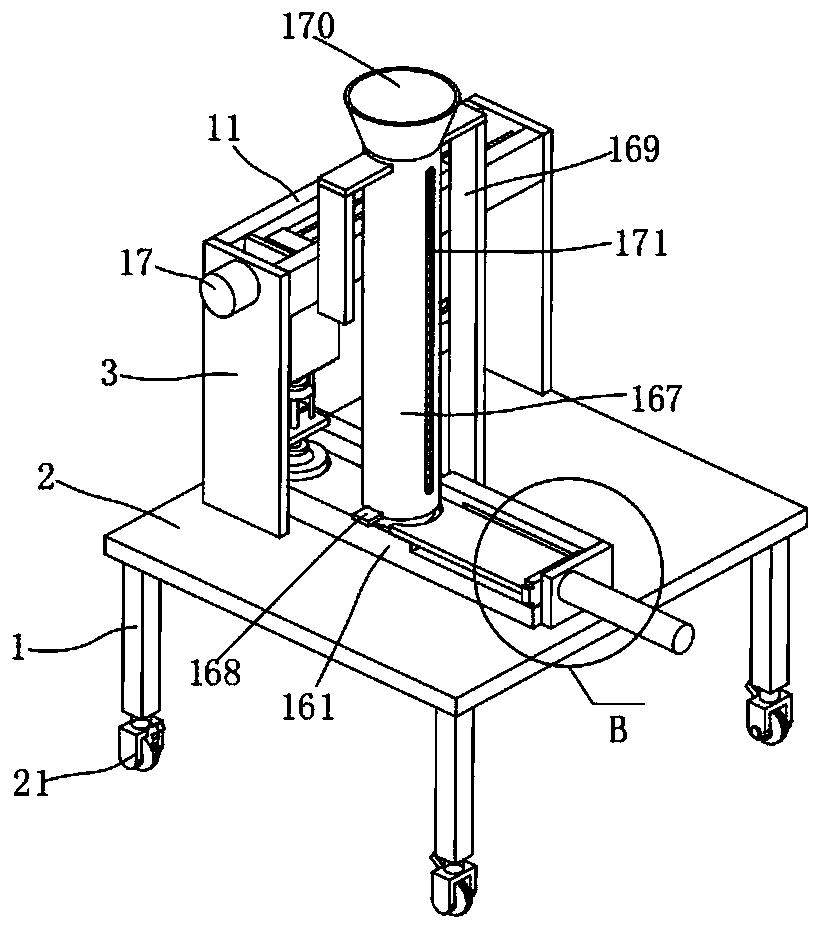
[0026] The present invention provides such Figure 1-6 The shown suction and release device for optical lenses includes a mounting frame 1, a mounting plate 2 is fixed on the upper end of the mounting frame 1, a first support plate 3 is fixed on one side of the mounting plate 2, and a first support plate 3 is fixed on the upper end of the...


PUM


Abstract

The invention discloses a suction lifting and releasing device for an optical lens. The suction lifting and releasing device comprises a mounting frame, and a mounting plate is fixed to the upper endof the mounting frame. First supporting plates are fixed to one side of the mounting plate, and a servo motor is fixed to the corresponding first supporting plate. A screw rod is fixed to an output shaft of the servo motor, and a driving nut is connected to the screw rod in a screw drive mode. The driving nut is inlaid in a mounting block, and first sliding blocks are arranged on both sides of themounting block. The first sliding blocks slide in first sliding grooves in fixing plates, and the fixing plates are fixed to the first supporting plates. A mounting box is fixed to the lower end of the mounting block, and a first air cylinder is fixed into the mounting box. A first connecting plate is fixed to a piston rod of the first air cylinder, and a vacuum chuck is fixed to the lower end ofthe first connecting plate. A feeding mechanism is arranged below the vacuum chuck. The automatic feeding is realized through the above structure, optical glass is automatically moved, the working efficiency is high, and the cost is saved.

Description

technical field [0001] The invention belongs to the technical field of suction and release devices for optical lenses, in particular to a suction and release device for optical lenses. Background technique [0002] Optical glass is mixed with oxides of high-purity silicon, boron, sodium, potassium, zinc, lead, magnesium, calcium, barium, etc. according to a specific formula, melted at high temperature in a platinum crucible, stirred evenly with ultrasonic waves, removed air bubbles, and then subjected to long-term The temperature is lowered slowly over time to avoid internal stress in the glass block. The cooled glass blocks must be measured by optical instruments to check whether the purity, transparency, uniformity, refractive index and dispersion rate meet the specifications. Qualified glass blocks are heated and forged to form optical lens blanks. [0003] Under the trend of international optoelectronic industry structure adjustment and industrial transfer, the world's...

Claims


Application Information

Patent Timeline
Patent Type & Authority Applications(China)
IPC IPC(8): B65G49/06
CPCB65G49/061B65G49/063
Inventor 曾明权谢炳高周兴华谢港谢炬谢华泽张竞孙小敏
Owner 江西高佳光电科技有限公司
Why Eureka
Try Eureka